Vehicle axle sensor

a technology of axle sensor and axle shaft, which is applied in the direction of cables, insulated conductors, ways, etc., can solve the problems of high manufacturing cost, poor performance, and inability to commercially succeed, and achieve the effect of reducing installation and retrieval time, high degree of flexibility, and easy disassembly

Inactive Publication Date: 2009-04-07
TRAFFIC MONITORING SERVICES
View PDF17 Cites 1 Cited by
  • Summary
  • Abstract
  • Description
  • Claims
  • Application Information

AI Technical Summary

Benefits of technology

[0005]Another object of the invention is to provide an improved roadway sensor that can be installed as easily and safely as a pneumatic “road-tube.”
[0008]The sensor has a high degree of flexibility so that the sensor assembly can be wound up on a reel so that it can be easily dispensed from a dispensing platform, thereby reducing the time to install and retrieve the sensor from the roadway.

Problems solved by technology

Most are not commercially successful due to high manufacturing costs, difficulties in installation procedures, poor performance and short usable life.
U.S. Pat. No. 5,360,953 is a good example of an overly complex arrangement of parts and high labor content to make one multi-lane sensor.
Its poor acceptance in the traffic industry is due in part because of its high manufacturing cost poor performance due to phantom switch closures caused by rubber extrusion bounce (sensor bounce) and the safety issue of making an installation.
Due to the multi-layers of conductive and non-conductive molded assemblies, wire and the outer rubber enclosure, the overall height of the completed assembly is relatively massive and dense causing vehicle suspension shock when a vehicle traverses the sensor in the roadway.
Also, reliability becomes a serious factor when consideration the numerous numbers of solder connections involved in the assembly process.

Method used


Image

  • Vehicle axle sensor
  • Vehicle axle sensor
  • Vehicle axle sensor

Examples


Embodiment Construction

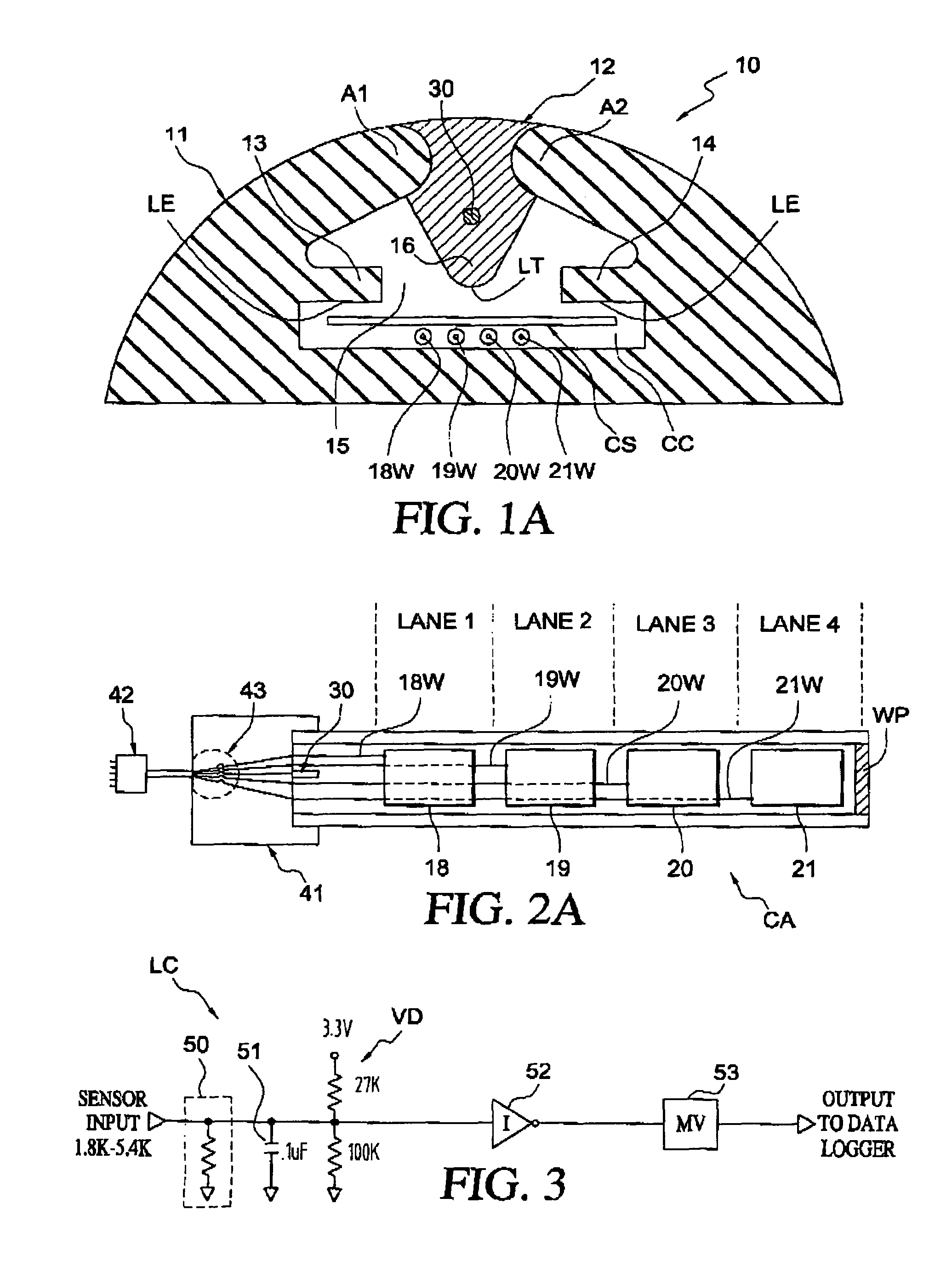
[0015]Referring to FIG. 1A, a one-piece tubular silicone rubber coextrusion 10 comprising a non-conductive silicone rubber 11 and a conductive silicone rubber 12. Other suitable materials may be used to make the coextrusion. Both rubber materials have a hardness of 80 durometer on the Type A scale. The linear conductive silicone rubber section 12 is formulated by mixing carbon particles with the non-conductive silicone rubber to achieve the required resistive values and proper bonding characteristics during the vulcanizing process when these two different rubber compounds are mutually joined and fused together during the coextrusion manufacturing process to form a deformable, closed housing. The inwardly projecting insulating wings 13 and 14 define a gap 15 through which the conductive contact protrusion or plunger 16 projects upon deformation of the housing. The rubber wedge removal spring arms A1, A2 serve two important sensitivity functions: (1) significantly improve the response...


PUM


Abstract

A roadway vehicle sensor includes a coextrusion having a linear conductive section and a linear non-conductive section forming a vehicle deformable closed housing. The linear conductive section has an inwardly projecting conductive plunger along the length thereof which is fused to wedge removal arms. The linear non-conductive section has a pair of inwardly projecting insulating wings having wing tips spaced apart a distance defining a plunger gap. The insulating wings also define a contact chamber into which the plunger protrudes only upon deformation of the vehicle deformable housing by a vehicle. Preferably, the vehicle deformable housing has a flat side on the exterior for engagement with a roadway surface. A contact assembly in the contact chamber has one or more flat conductive lane switch segment, each flat conductor lane switch segment having a width which avoids phantom switch closures.

Description

REFERENCE TO RELATED APPLICATION[0001]This application claims the benefit of provisional application No. 60 / 697,948, filed Jul. 12, 2005 entitled Multi-Lane Vehicle Axle Sensor.BACKGROUND OF THE INVENTION[0002]Various devices for counting the number of vehicles traveling on a roadway are known in the patented art. The invention described is based on the principle of an “active high impedance” switch closure. The majority of the prior art in this category rely in the contact members to be separated by non-conductive material or embedded in either a non-conductive or conductive material in order to separate the lane signals. Most are not commercially successful due to high manufacturing costs, difficulties in installation procedures, poor performance and short usable life. U.S. Pat. No. 5,360,953 is a good example of an overly complex arrangement of parts and high labor content to make one multi-lane sensor. Its poor acceptance in the traffic industry is due in part because of its hig...

Claims


Application Information

Patent Timeline
Patent Type & Authority Patents(United States)
IPC IPC(8): G08G1/01
CPCE01F11/00G08G1/02
Inventor TYBURSKI, ROBERT M.
Owner TRAFFIC MONITORING SERVICES
Why Eureka
Try Eureka