
Piezooscillator

a technology of piezoelectric vibrators and heating elements, applied in the field of piezoelectric vibrators, can solve the problems of difficult application, difficult to realize the downsizing and height reduction of ocxo, and easy to affect the tcxo, so as to reduce the space to accommodate the piezoelectric vibrators and the heating element, reduce the size and height of the piezoelectric vibrator, and prevent the effect of heating element hea

Inactive Publication Date: 2009-04-07
NIHON DEMPA KOGYO CO LTD
View PDF3 Cites 31 Cited by
  • Summary
  • Abstract
  • Description
  • Claims
  • Application Information

AI Technical Summary

Benefits of technology

The present invention provides a piezooscillator with a heating element that can be easily assembled and reduce power consumption by reducing the size and height of the piezooscillator. The piezoelectric vibrator is accommodated in a recess on the substrate and is supported by a supporting member. The heating element is provided on the surface of the piezoelectric vibrator and a temperature sensor controls power supply to the heating element based on the output of the temperature sensor. The piezooscillator is easy to produce and has a simplified production process. The technical effects of the invention include reducing the size and height of the piezooscillator, reducing power consumption, and simplifying the production process.

Problems solved by technology

As compared to OCXO, however, the TCXO is easily affected by the ambient temperature and hence difficult to apply when high frequency stability is required.
It is therefore difficult to realize the downsizing and height reduction of the OCXO and, therefore, the OCXO has a height, for example, of approximately 7 mm to 10 mm at minimum.
Accordingly, due to an addition of a soldering step or the like, the production process of the OCXO becomes complicated and production cost increase is caused, being problems.
Further, the heat of the heating element 13 is released to the substrate 11, causing a problem of increasing power consumption to keep the quartz vibrator 12 be at a preset temperature.

Method used


Image

  • Piezooscillator
  • Piezooscillator
  • Piezooscillator

Examples


Embodiment Construction

)

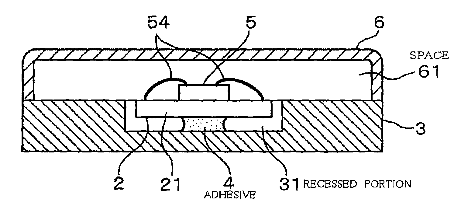
[0033]Hereinafter, as an example embodiment of a piezooscillator according to the present invention, a quartz oscillator provided with a quartz vibrator will be described with reference to the drawings. FIGS. 1A, 1B, 1C are views showing a sectional plane, a side section and a rear surface of the quartz oscillator, respectively. In the drawings, “2” denotes the quartz vibrator, “3” denotes a substrate, “4” denotes an adhesive, “5” denotes an integrated circuit and “6” denotes a cover, and these are components of the quartz oscillator.

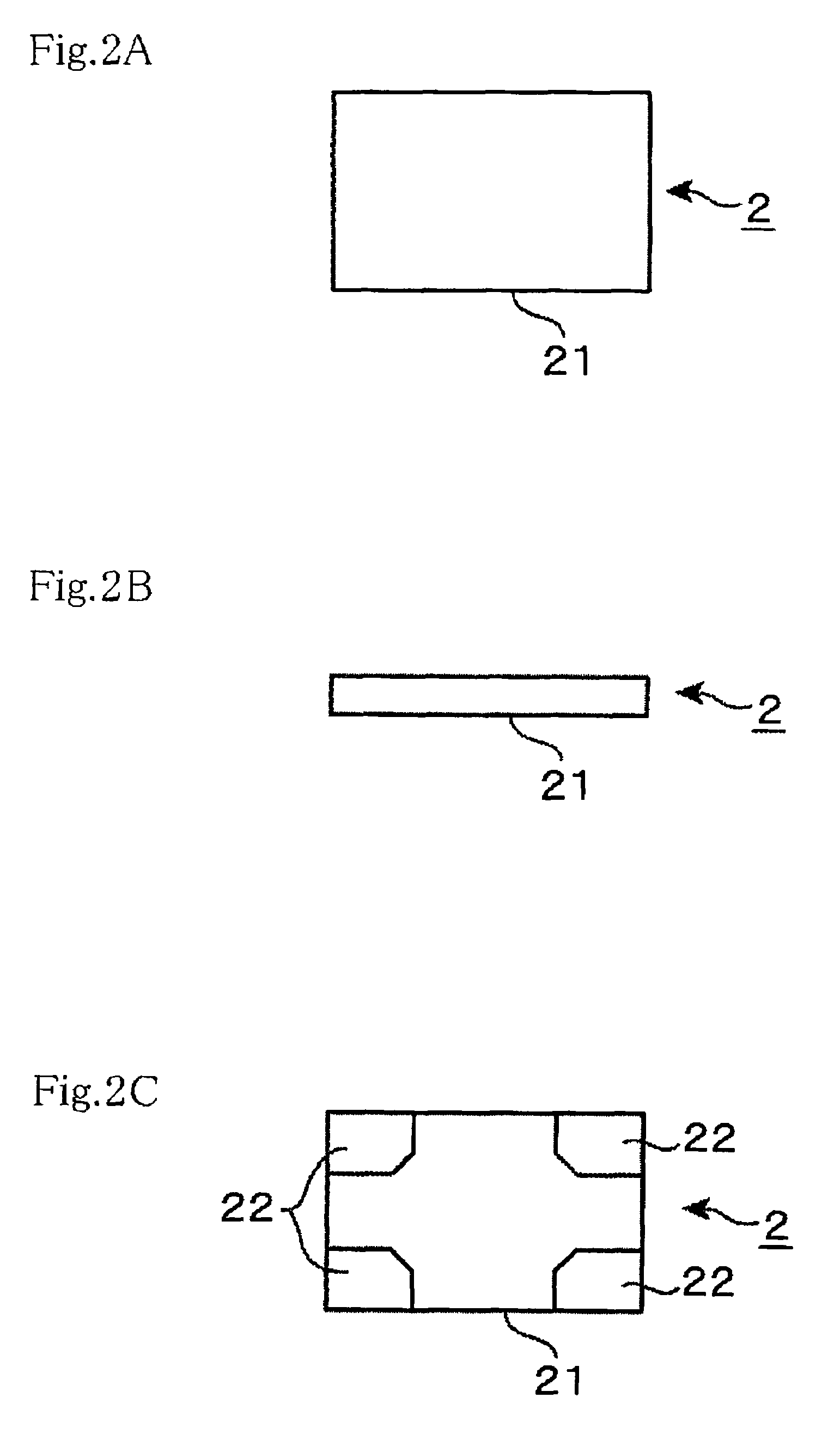
[0034]FIGS. 2A, 2B, 2C are views showing the quartz vibrator 2 being a piezoelectric vibrator, and in this example, a quartz crystal piece and a pair of exciting electrodes to excite the quartz crystal piece are enclosed in a card-type package 21. Electrodes 22 are provided, for example, at four corners on a surface of the package 21, and the respective electrodes 22 are electrically connected to the exciting electrodes respectively inside the package ...


PUM


Abstract

A piezooscillator having a piezoelectric vibrator and an oscillation circuit in a space surrounded by a substrate and a cover, which has a smaller size and height, and further, which can be assembled easily and suppress power consumption, is provided. The piezooscillator includes a recessed portion formed on the surface of the substrate; a supporting member supporting the piezoelectric vibrator while the piezoelectric vibrator is in a state partially or entirely accommodated in the recessed portion and floating from the substrate; a heating element provided on the surface of the piezoelectric vibrator; a temperature sensitive element provided in the space; and a temperature control unit provided in the space and controlling power supply to said heating element based on an output of the temperature sensitive element, in which, it is possible to reduce capacity of the space accommodating the piezoelectric vibrator and the heating element by eliminating the need of an additional substrate provided above the substrate as in conventional piezoelectric vibrators, so that the size and height of the piezooscillator can be reduced, in which assembling is eased, and power consumption can be reduced on the back of suppressed heat release to the substrate.

Description

BACKGROUND OF THE INVENTION[0001]1. Field of the Invention[0002]The present invention relates to a piezooscillator provided with a piezoelectric vibrator and configured to stabilize frequency oscillated by the piezoelectric vibrator against a change in ambient temperature using a heating element.[0003]2. Description of the Related Art[0004]As an example of the piezooscillator provided with the piezoelectric vibrator, there is a quartz oscillator provided with a quartz vibrator, and as typical configurations to obtain frequency stability against the temperature of the crystal oscillator, there are known a TCXO (Temperature Compensated Crystal Oscillator) and an OCXO (Oven Controlled Crystal Oscillator) (Nonpatent document 1). The TCXO is configured to have a built-in temperature compensation circuit employing a temperature sensitive element so that the oscillation frequency is corrected based on the value of the temperature detected by the temperature sensitive element. This TCXO has...

Claims


Application Information

Patent Timeline
Patent Type & Authority Patents(United States)
IPC IPC(8): H01L41/08H10N30/00
CPCH03H9/0514H03H9/0542H03H9/0552H03H9/08H03H9/1014
Inventor KASAHARA, KENJIUCHIDA, TAKESHI
Owner NIHON DEMPA KOGYO CO LTD
Learn More