
Self-cooled rotor for an electrical machine

a self-cooled, electric machine technology, applied in the direction of dynamo-electric machines, electrical apparatus, magnetic circuits, etc., can solve the problems of increasing friction losses, adversely affecting the performance of both permanent magnets and carbon fibre sleeves, and increasing pressure gradients over the length of the rotor, so as to avoid high pressure and temperature gradients in the rotor and improve performance.

Active Publication Date: 2009-04-07
TURBO POWER SYST
View PDF7 Cites 9 Cited by
  • Summary
  • Abstract
  • Description
  • Claims
  • Application Information

AI Technical Summary

Benefits of technology

"The present invention provides a rotor for an electric machine with an internally cooled design that requires minimal external pumping of cooling fluid. The rotor has a main body with magnetic field generating means and a first channel that extends axially into the rotor. The rotor also has one or more second channels that extend radially outward from the first channel. The second channels can communicate cooling fluid to the outer surface of the rotor. The cooling fluid flows through the channels and is pumped outwards by the rotation of the rotor. The amount of cooling fluid can be controlled to provide sufficient cooling to the rotor without causing excessive windage losses. The design of the channels allows for a dual cooling action and can improve cooling efficiency."

Problems solved by technology

Rotors in high speed machines are generally operated in an environment where both mechanical frictional losses (windage) and electrical current losses (eddy currents) contribute to the heating of the rotor during operation.
However, any material that sits in the air gap between the magnets on the rotor and the stator will be subject to these harmonics, generating losses due to eddy currents in these materials.
However, even with the use of a high resistivity carbon fibre sleeve, there is still a need to consider the cooling of the magnet material and any pole spacers that sit between the magnets, as these will also be subject to heat build up due to electrical losses.
Problems can therefore occur when the rotor is relatively long, as this leads to a pressure gradient building up over the length of the rotor.
Higher temperatures will adversely affect the performance of both the permanent magnets and the carbon fibre sleeve, and therefore the temperature at the hot end of the shaft will be the determining factor in the required flow rate of cooling air.
Increasing the mass flow rate of cooling air through the gap to limit the temperature rise will normally cause the friction losses to increase, compounding the problem.
An additional problem with the known methods of cooling rotors in high speed machines is that the carbon fibre sleeve acts as a thermal insulator for the magnets and rotor structure underneath.
Therefore, any heat produced from electrical losses in the rotor under the sleeve will be more difficult to remove using the air forced over the outer diameter of the sleeve.
In addition, with known methods, the pressure ratio required to move sufficient cooling air through the radial air gap needs to be generated from an external source such as a cooling fan or by virtue of other means, which increases the cost and complexity of the system.

Method used


Image

  • Self-cooled rotor for an electrical machine
  • Self-cooled rotor for an electrical machine
  • Self-cooled rotor for an electrical machine

Examples


Embodiment Construction

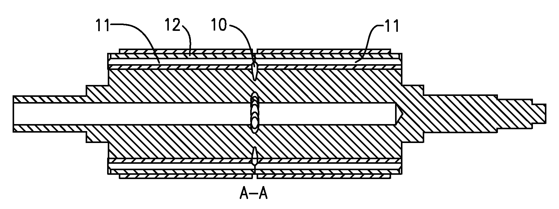
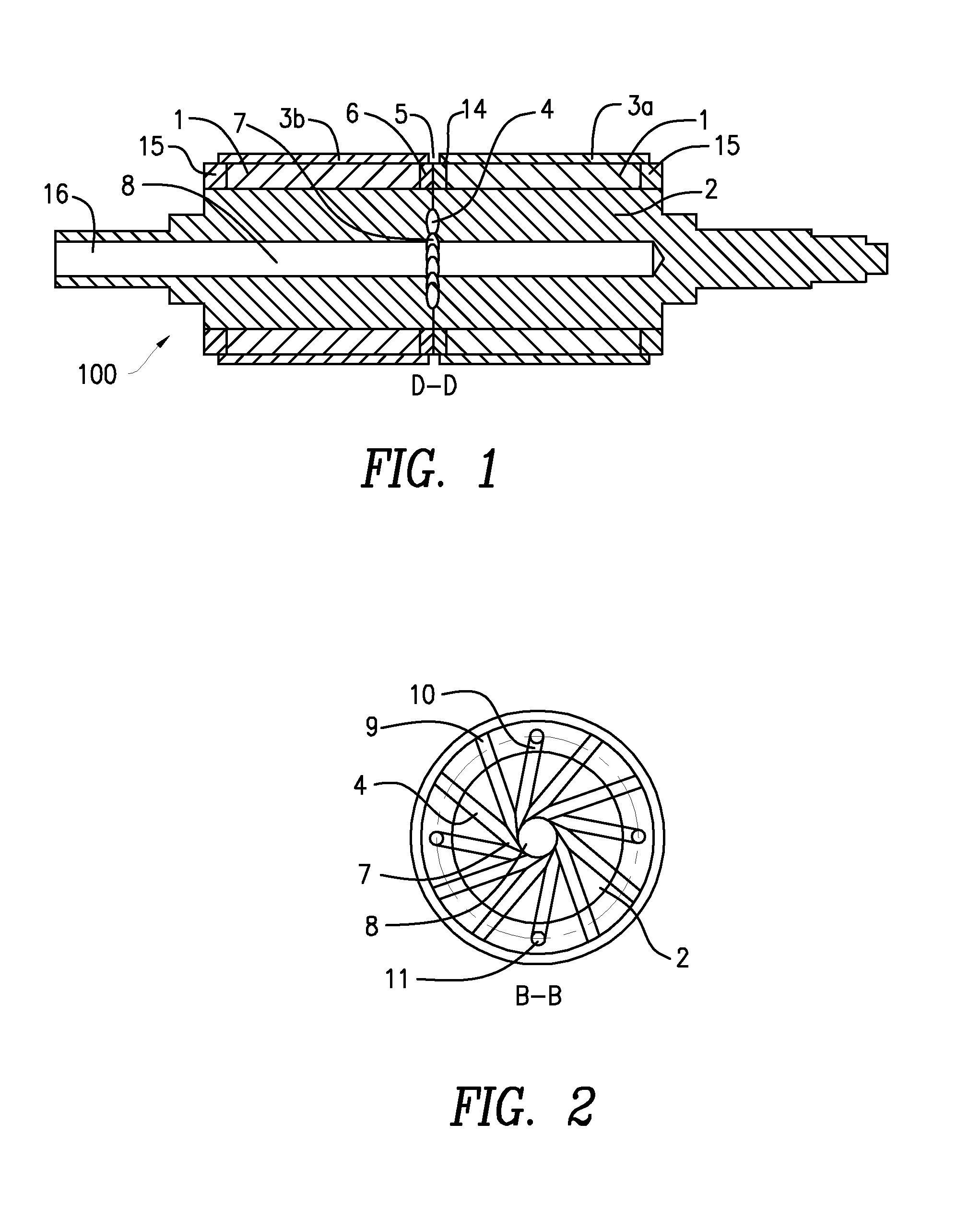
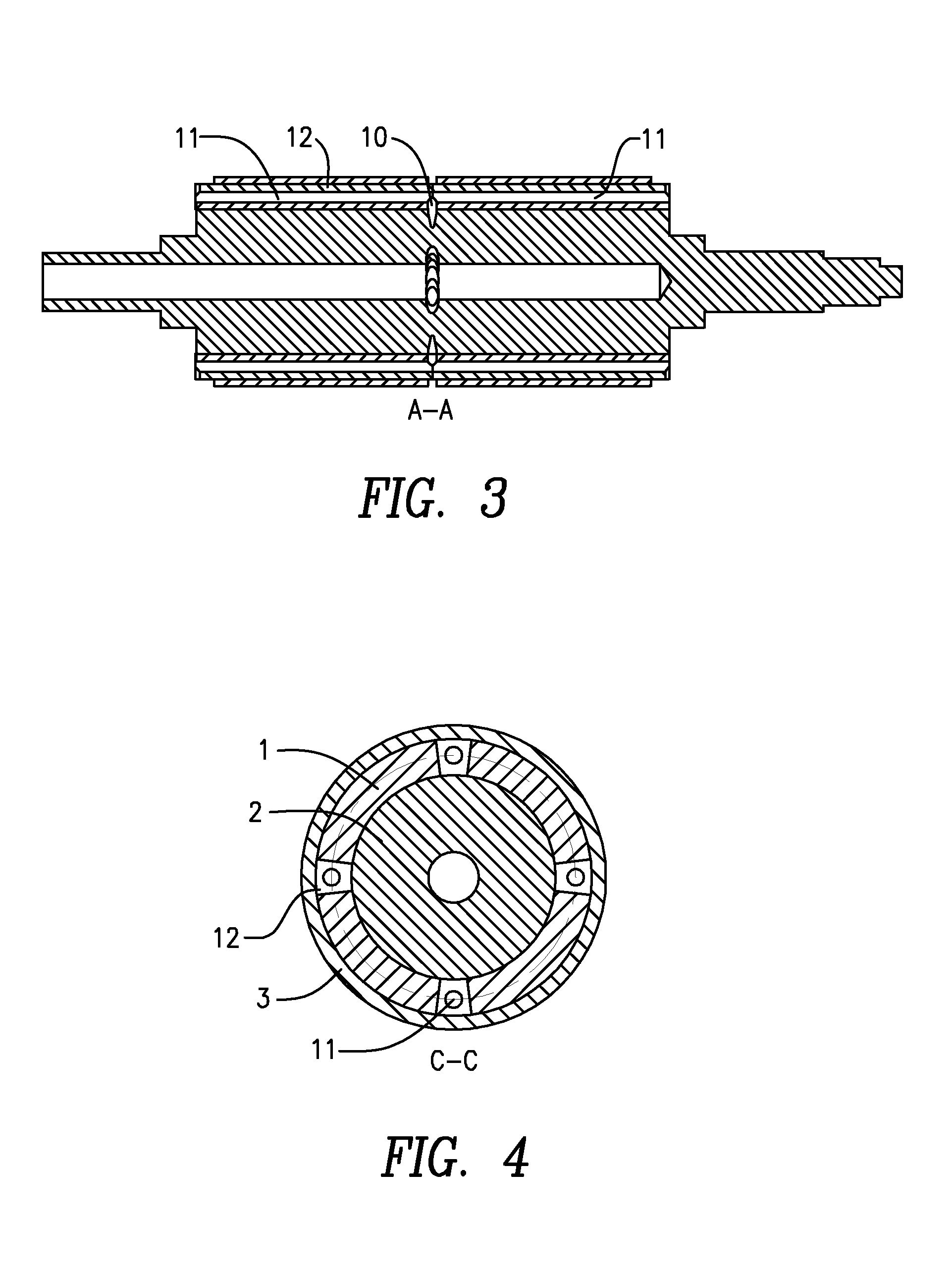
[0027]FIG. 1 shows an axial cross-section of a rotor 100. The rotor 100 has a generally cylindrical core 2 comprising an axial channel 8 defining a generally cylindrical blind aperture. Permanent magnets 1, which are typically constructed from a rare earth metal, are mounted to the core 2 and project a magnetic field radially outwards from the core 2. The magnets 1 are arranged in two sections with an axial gap between the sections. Axial spacers 6 are provided in the axial gap. The magnets are separated by pole spacers 12, shown in cross-section in FIG. 4, which are typically made from a non-magnetic material that has high thermal conductivity to extract heat from the magnets. The axial spacers 6 are constructed of the same material as the pole spacers 12. The axial spacers 6 and the pole spacers 12 together with additional annular sections 15 at the outer ends of the rotor form a support frame around each pole of the magnets 1. The support frame is configured as a single piece str...


PUM


Abstract

A self-cooled rotor for an electrical machine being internally provided with a cooling channel to carrying cooling fluid. The machine includes a further channel for carrying cooling fluid in proximity to a magnetic field generating means for cooling it, the two passages being connected to each other within the machine.

Description

FIELD OF THE INVENTION[0001]The present invention generally relates to a self-cooled rotor, in particular for a high speed permanent magnet electric machine, such as a generator.BACKGROUND OF THE INVENTION[0002]Rotors in high speed machines are generally operated in an environment where both mechanical frictional losses (windage) and electrical current losses (eddy currents) contribute to the heating of the rotor during operation. Therefore cooling of the rotor in such machines is an important factor when considering their design.[0003]In a radial flux machine, the rotor is often configured as a drum, rotating inside an annular stator assembly, with shaft bearings at either end of the drum. Rare earth permanent magnets are typically mounted to the shaft of the rotor and project an electromagnetic field radially outwards from the drum in a pattern determined by the number and shape of the magnetic poles. As these machines operate at high surface speeds (over 150 m / s), it is generally...

Claims


Application Information

Patent Timeline
Patent Type & Authority Patents(United States)
IPC IPC(8): H02K1/32
CPCH02K1/32H02K9/04H02K1/274
Inventor HALL, JUSTIN ARTHUR
Owner TURBO POWER SYST
Learn More