
Method for starting a sensorless, electronically commutatable direct current motor

a direct current motor and sensorless technology, applied in the direction of electronic commutators, motor/generator/converter stoppers, dynamo-electric converter control, etc., can solve the problem of becoming very complex the known method

Inactive Publication Date: 2009-03-31
ROBERT BOSCH GMBH
View PDF12 Cites 16 Cited by
  • Summary
  • Abstract
  • Description
  • Claims
  • Application Information

AI Technical Summary

Benefits of technology

Enables reliable, regulated startup and operation of direct current motors under varying loads with minimal engineering effort, rapid detection of motor blocking, and efficient speed governance, using a simple and economical control system that reduces computational requirements.

Problems solved by technology

After the startup of the machine and especially at high rpm, however, this known method becomes very complex and requires a very high-powered, fast computer for ascertaining the current rotor position at the time, knowledge of which is necessary for the regulation.

Method used


Image

  • Method for starting a sensorless, electronically commutatable direct current motor
  • Method for starting a sensorless, electronically commutatable direct current motor
  • Method for starting a sensorless, electronically commutatable direct current motor

Examples


Embodiment Construction

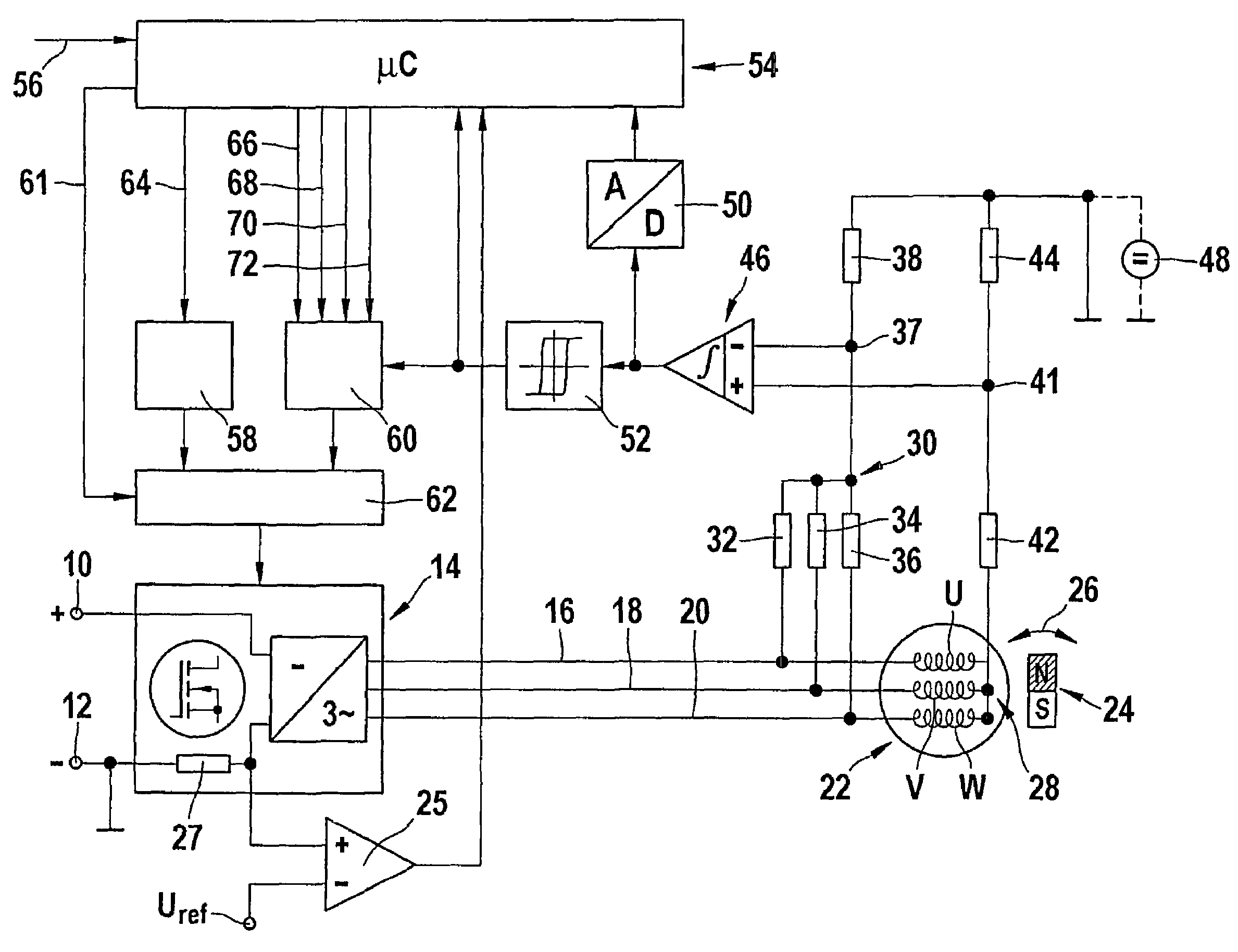
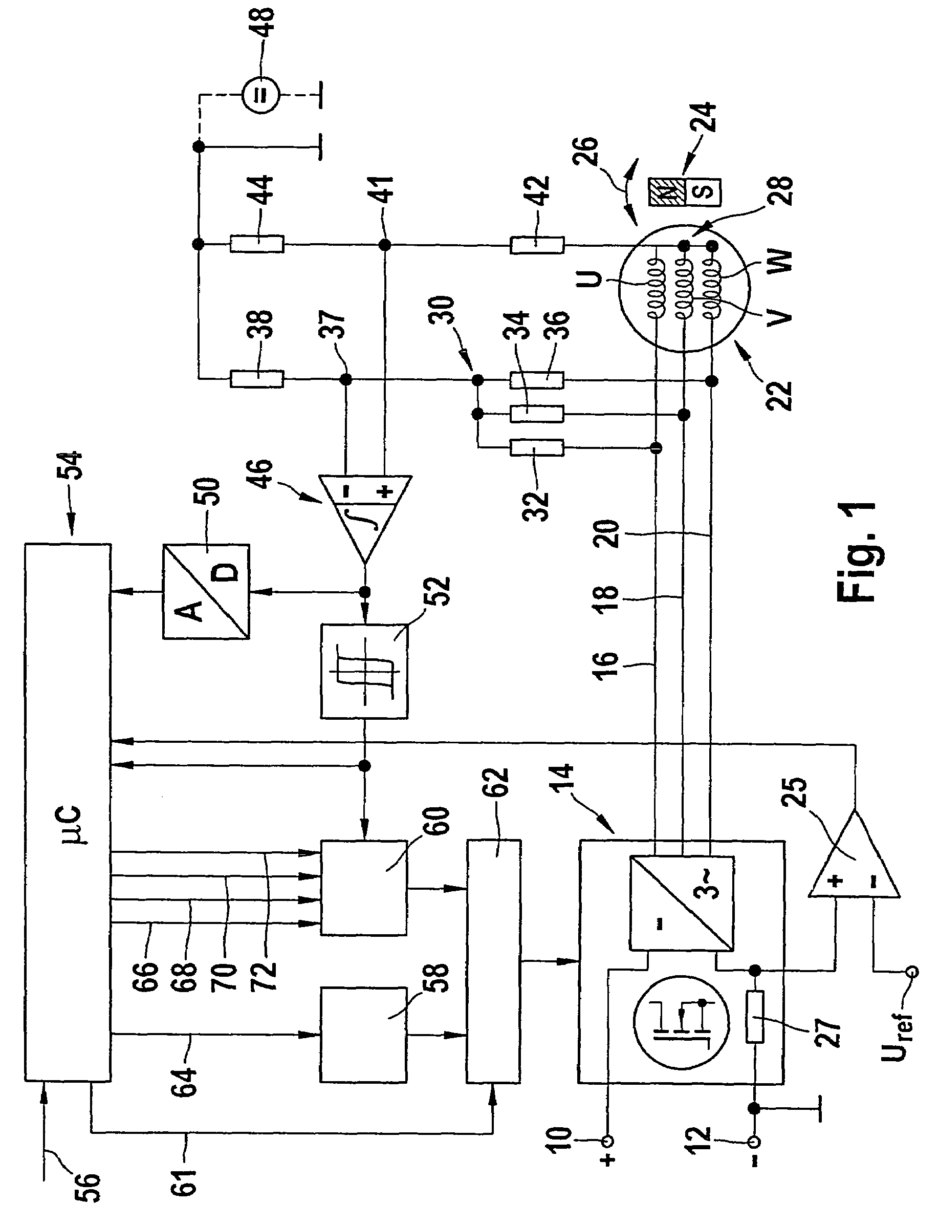
[0014]In FIG. 1, 10 designates the positive pole and 12 the negative pole, connected to ground, of a direct voltage source, which supplies an inverter 14 constructed as a six-pulse converter bridge with MOSFET transistors. The outputs of the inverter are connected via leads 16, 18, 20 to the phase windings U, V, W of the stator 22 of a sensorless, electronically commutatable direct current motor, whose permanent-magnetically excited rotor is shown at 24. A double arrow 26 at the rotor 24 indicates that the rotor can be driven in opposite directions of rotation.

[0015]Via a further output of the inverter 14, the current in the direct voltage circuit, upon the imposition of current pulses on the phase windings U, V, W, is delivered to a measuring shunt 27, connected to ground, for ascertaining the rotor position at standstill of the machine. The voltage drop at the shunt 27 is compared in a comparator 25 with a reference voltage Uref, and the output signal of the comparator 25 is deliv...


PUM


Abstract

A method for starting a sensorless, electronically commutatable direct current motor, having a permanent-magnetically excited rotor in which the stator carries a three-phase stator winding, whose regulated supply of current from a direct voltage source is already made possible from the standstill state. To that end, by the control device used, at rotor standstill and at the onset of the startup operation in the range below a minimum value of the rotor rpm, first the position of the rotor is ascertained, and then via the switching device, a regulated initial supply of current to the phase windings of the stator is generated, while after the predetermined minimum value of the rotor rpm is attained, the control device receives position signals as rotor position signals for a self-commutation of the motor, which signals are derived directly from the third and / or further odd-numbered harmonics of the phase voltages, and from these position signals furnishes control signals to the switching device for supplying current to the phase windings in normal operation.

Description

CROSS-REFERENCE TO RELATED APPLICATION[0001]This application is a 35 USC 371 application of PCT / EP 2005 / 050480 filed on Feb. 4, 2005.BACKGROUND OF THE INVENTION[0002]1. Field of the Invention[0003]The invention relates to a method for starting a sensorless, electronically commutatable direct current motor.[0004]2. Description of the Prior Art[0005]One method of starting electronically commutated direct current motors is known for instance from the dissertation D 93 by Volker Bosch at the University of Stuttgart, entitled “Elektronisch kommutiertes Einzelspindelantriebssystem” [Electronically Commutated Single-Spindle Drive System], Shaker Verlag, Aachen, 2001. In such electronically commuted direct current motors, which do not detect the rotor position via sensors, the absolute position of the rotor at a standstill is not known. For initial positioning of the motor, the rotor is therefore first put in a predetermined outset position at the onset of the startup operation, which is do...

Claims


Application Information

Patent Timeline
Patent Type & Authority Patents(United States)
IPC IPC(8): H02P25/08H02P6/18H02P6/22
CPCH02P6/182H02P6/185H02P6/22H02P29/021H02P29/0241
Inventor BOSCH, VOLKERWIRNITZER, BERND
Owner ROBERT BOSCH GMBH
Learn More