
Automatic flush actuation apparatus

a technology of automatic flushing and actuation apparatus, which is applied in the direction of mechanical apparatus, urinals, valve operating means/releasing devices, etc., can solve the problems of failure to operate the flush valve, the structural design of the solenoid operated automatic flushing valve is different from that of the and the maintenance cost of the solenoid operated automatic flushing valve is higher than that of the conventional manual operation flushing valve. to achieve the effect of improving the reliability of operation

Inactive Publication Date: 2009-03-31
MAERCOVICH JORGE +2
View PDF13 Cites 14 Cited by
  • Summary
  • Abstract
  • Description
  • Claims
  • Application Information

AI Technical Summary

Benefits of technology

[0011]A main object of the present invention is to provide an automatic flush actuation apparatus which is adapted to control a flow of water by an electric motor, so as to enhance the reliable of the operation of the automatic flush actuation apparatus.
[0015]Another object of the present invention is to provide an automatic flush actuation apparatus which is reliable and that can be easily installed and maintained.
[0016]Another object of the present invention is to provide an automatic flush actuation apparatus, wherein a covering cap has a battery opening that allows a power source exposing to outside. Therefore, any individual is able to simply replace the power source without detaching the covering cap from the flushing system, so as to reduce the maintenance cost of the present invention.
[0017]Another object of the present invention is to provide an automatic flush actuation apparatus, wherein the covering cap further has a sensor opening that allows a CPU exposing to outside. Therefore, any individual is able to make adjustments via the sensor switch through the CPU opening without detaching the covering cap from the flushing system.
[0018]Another object of the present invention is to provide an automatic flush actuation apparatus, which is powered by an electric motor so as to avoid water damage and to enhance performance and reliability.
[0019]Another object of the present invention is to provide an automatic flush actuation apparatus, which provides an economic and efficient solution for incorporating with the conventional manual operated flushing system in a simple and economical way.

Problems solved by technology

However, the flush valves, according to the above patents, have several common drawbacks.
It is one of the common problems to cause a failure of operation of the flush valve.
Thus, the maintenance cost of the solenoid operated automatic flush valve is higher than that of the conventional manual operated flush valve.
In addition, the structural design of the solenoid operated automatic flush valve is different from that of the manual operated flush valve.
In other words, when the flushing system is incorporated with the solenoid operated automatic flush valve, the flushing system will lose the mechanical-manual operated feature.
Therefore, there is no alternative to operate the flushing cycle when the solenoid operated automatic flush valve has failed to operate.
In order to install the solenoid operated automatic flush valve into the conventional flushing system, the mechanical-manual operating mechanism of the flush valve must be totally removed, which is a waste of resources in order to incorporated with the solenoid operated automatic flush valve.
The configuration of the solenoid operated automatic flush valve is complicated, wherein once the solenoid is broken or the battery is dead, the facility should call a technician to open an outer cover and disassemble an inner cover for the replacement of the solenoid or the battery.
Due to the complicated structure of the solenoid operated automatic flush valve, the solenoid operated automatic flush valve requires a skilled technician to replace the broken solenoid and / or even replace the battery, which may further increase the maintenance cost of the infrared operated automatic flush valve.

Method used


Image

  • Automatic flush actuation apparatus
  • Automatic flush actuation apparatus
  • Automatic flush actuation apparatus

Examples


Embodiment Construction

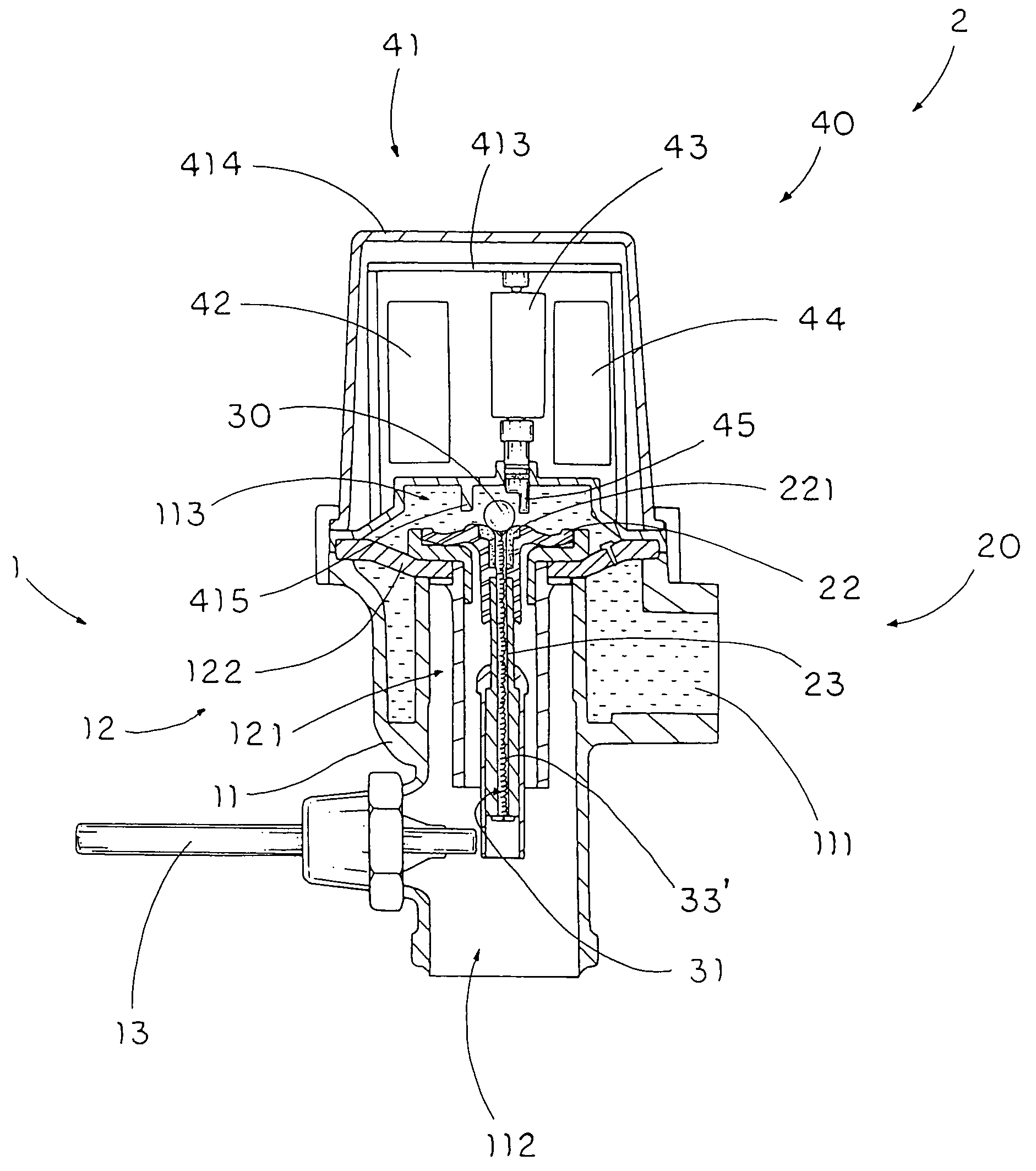
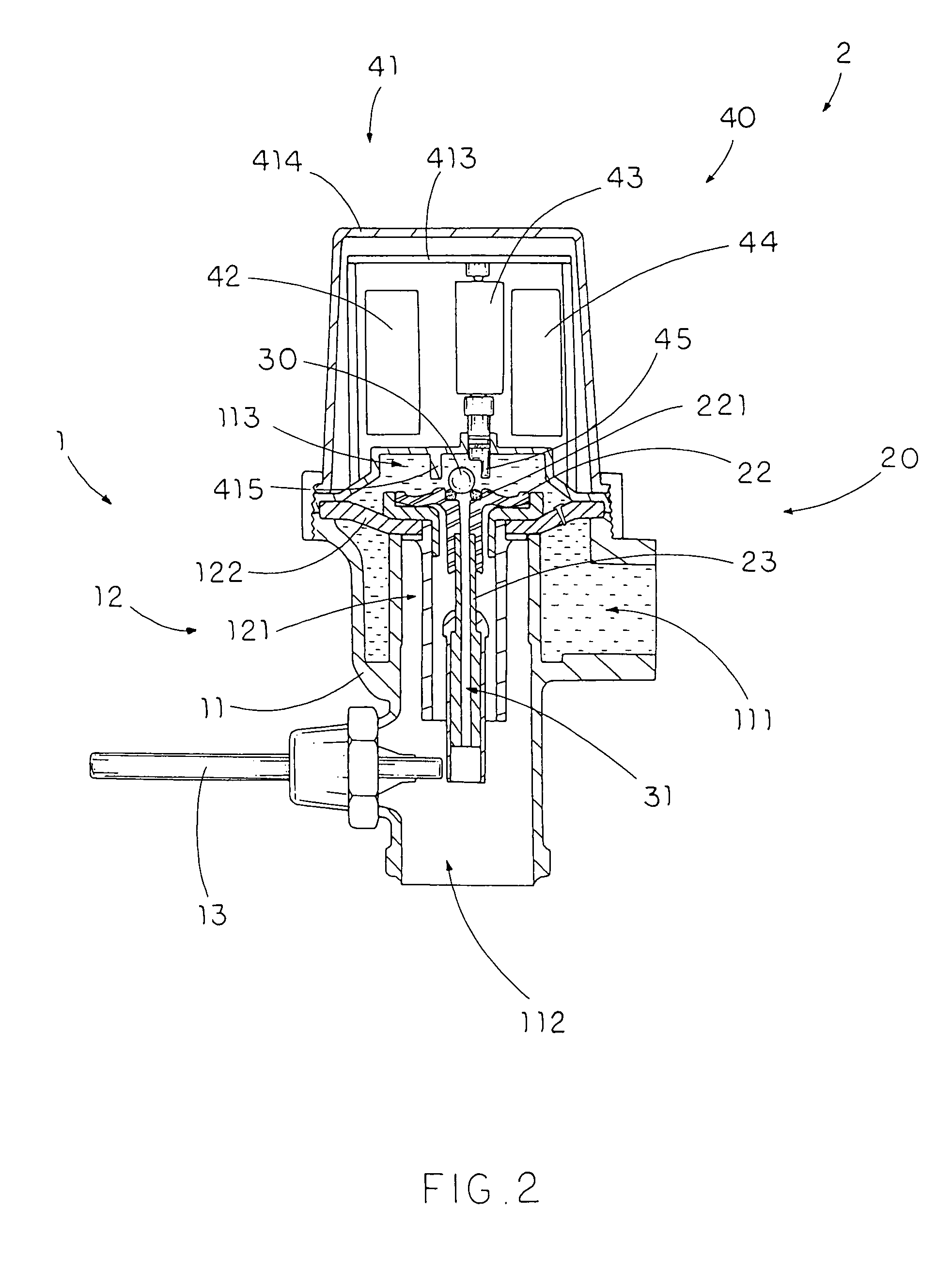
[0035]Referring to FIG. 2 of the drawings, an automatic flush actuation apparatus 2 for a flushing system 1 according to a preferred embodiment of the present invention is illustrated, wherein the automatic flush actuation apparatus 2 is capable of incorporating with a conventional manual operated flushing system to achieve both manual and automatic operations to start a flushing cycle of the flushing system 1.

[0036]The flushing system 1, such as the conventional manual operated flushing system, comprises a valve body 11 having a water inlet 111, a water outlet 112 and a water chamber 113 that is normally sealed between the water inlet 111 and the water outlet 112, a valve seat 12, having a flush channel 121, disposed between the water inlet 111 and the water outlet 112 to block water flowing from the water inlet 111 to the water outlet 112, and a flush lever 13 coupled with the valve body 11.

[0037]The valve seat 12 comprises a diaphragm 122, having a bleed hole 100, sealedly dispos...


PUM


Abstract

An automatic flush actuation apparatus, which is incorporated with a flushing system having a water inlet, a water outlet, and a water chamber communicating therebetween, that includes a valve member being moved by a flush lever for releasing the water pressure within the water chamber to allow the water passing from the water inlet to the water outlet, and a sensor-operated powering assembly including a relief valve provided at the valve member for controlling the water flowing to the water outlet and an actuator arranged in such a manner that while sensing a presence of a user of the flushing system, the actuator is driven to move the relief valve to an opened position for releasing the water pressure within the water chamber to allow the water passing to said water outlet.

Description

CROSS REFERENCE OF RELATED APPLICATION[0001]This is a Continuation-In-Part application of a non-provisional application, having an application Ser. No. 11 / 004,704 and a filing data of Dec. 3, 2004 now U.S. Pat. No. 7,028,977.BACKGROUND OF THE PRESENT INVENTION[0002]1. Field of Invention[0003]The present invention relates to a toilet and urinal facility, and more particularly to an automatic flush actuation apparatus which is capable of incorporating with a conventional commercial manual restroom flushing system, such as urinal and water closet, so as to selectively operate the automatic flush actuation apparatus automatically through the use of a sensor or normally through an actuation lever.[0004]2. Description of Related Arts[0005]Manual operated toilet room flush valves for use on urinals and water closets in public restrooms are well known. As shown in FIG. 1, a conventional manual operated automatic flush actuation apparatus comprises a valve body A1 having a water inlet A11 an...

Claims


Application Information

Patent Timeline
Patent Type & Authority Patents(United States)
IPC IPC(8): E03D5/10
CPCE03D3/06E03D5/10F16K31/3855F16K31/404
Inventor MAERCOVICH, JORGEMAERCOVICH, LEOLIU, SHAO-KUANG
Owner MAERCOVICH JORGE
Learn More