
Table bridge

a technology for connecting tables and bridges, which is applied in the field of bridges for connecting tables, can solve the problems of inability to combine round tables efficiently, difficulty in use, and limited number of tables

Inactive Publication Date: 2009-03-31
EAGLE FRLIN
View PDF14 Cites 10 Cited by
  • Summary
  • Abstract
  • Description
  • Claims
  • Application Information

AI Technical Summary

Benefits of technology

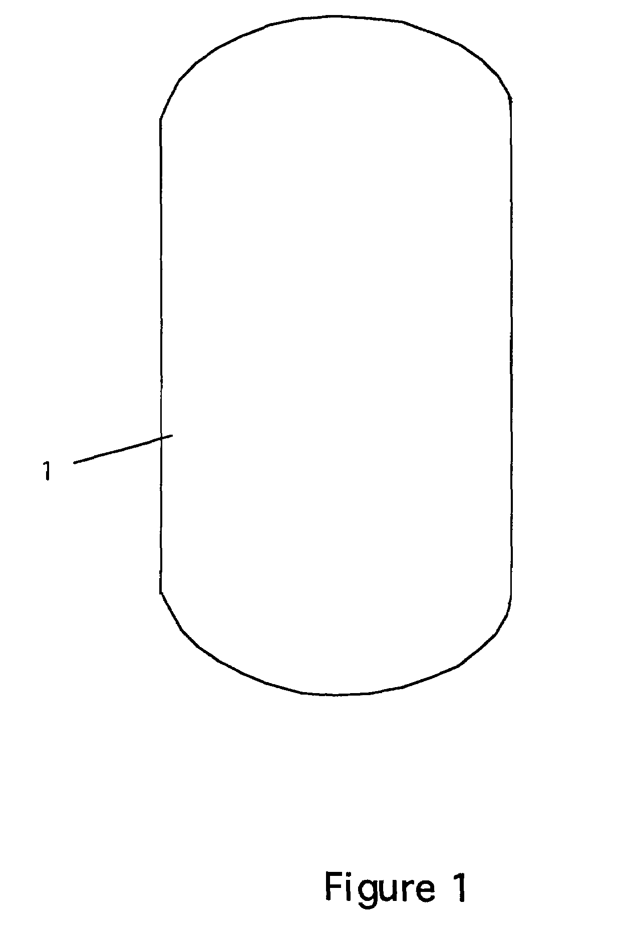
[0010]Thus, the bridges serve as a decorative hanging that can be customized with different materials and different look. They can be removed from the wall, to join two round tables, that might seat a combined total of eight people, to form a table that will now comfortably seat 12 people.

Problems solved by technology

Although these tables are useful, they are difficult to use when trying to accommodate large groups.
This causes problems because the number of tables is limited and the round tables cannot be combines efficiently.
Thus, system does not provide additional space after the tables are joined.
The problem with all of these devices is that they are either permanent or semi-permanent attachments.
Moreover, no one would suggest that these table conversions be done on the spot-they require tools and workers to assemble and fasten the parts together-not the kind of atmosphere most restaurants aspire to during meals.

Method used


Image

  • Table bridge
  • Table bridge
  • Table bridge

Examples


first embodiment

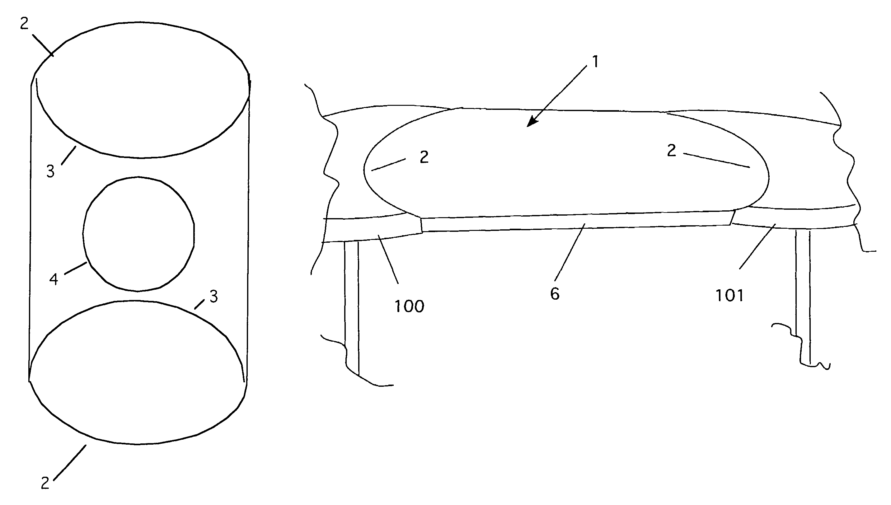
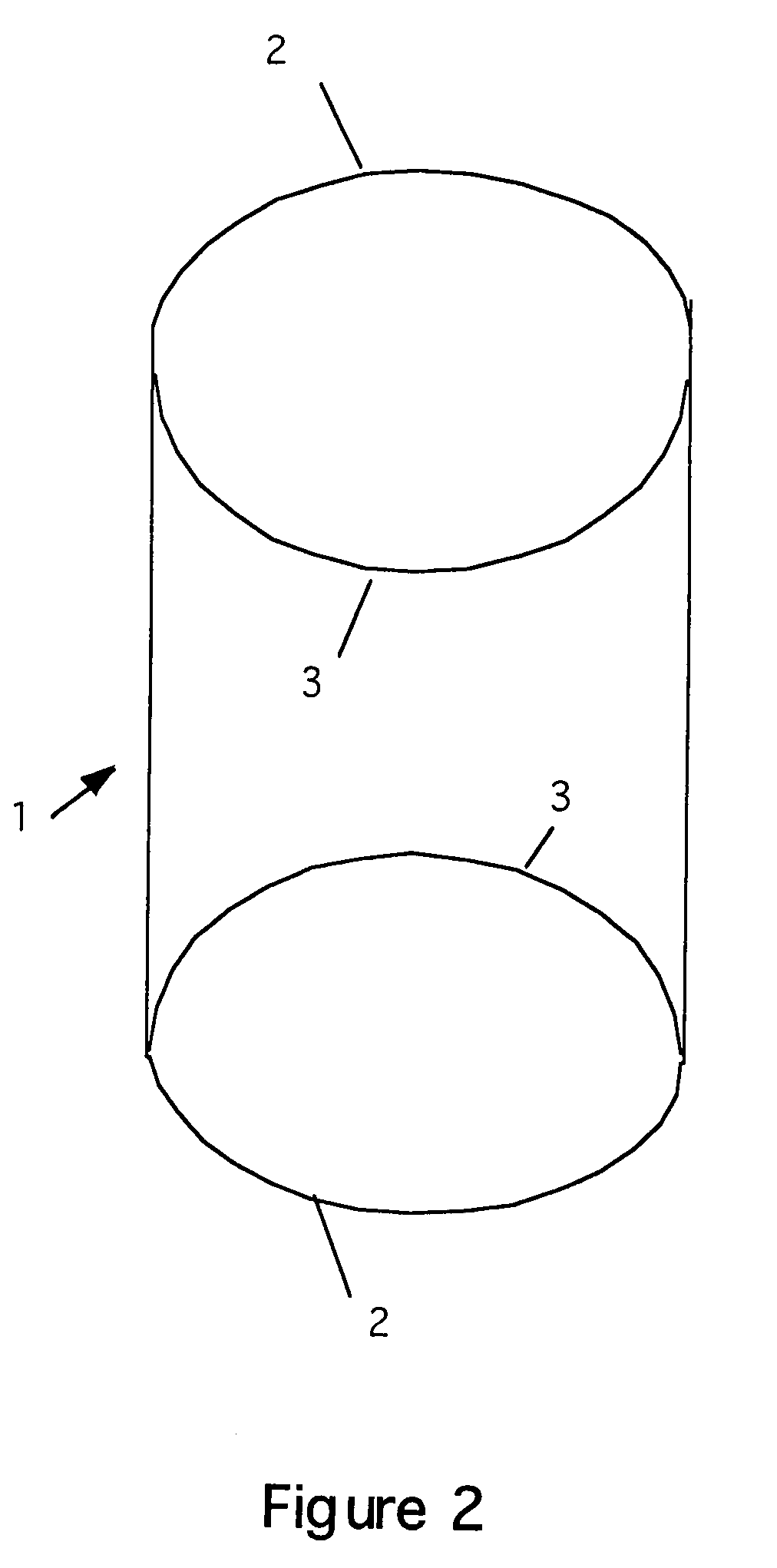
[0021]FIG. 2 is a bottom view of the invention 1. The bottom has two curved sections 3 that form the brace portions. These portions extend downward (see FIG. 4). The radii of the curved sections 3 match that of the round table the bridge is joined. For example, a 36-inch diameter table uses a bridge with curved portions of a 36-inch diameter radius. Note that the curved edges 2 are flat and lie atop the tables when the bridge is set in place.

second embodiment

[0022]FIG. 3 is a bottom view of the invention. In this embodiment, the curved portions 3 are installed as normal. However, an extra form 4 is added in the center. The center form 4 is designed to fit over smaller round tables (e.g., 20 inches dia.) In this way, a bridge can be used to expand a single small table.

[0023]FIG. 4 is a bottom perspective view of two bridges being combined together to make a larger table structure. This system is used with the second embodiment. Here, two small tables are joined by placing the center forms 4 of two bridges on two tables. The tables are then brought together until the end 2 of one bridge overlaps the end 2 of the second bridge. The ends of the bridges are secured by clamps 5 that are slid into place. Note also that in this figure, the edge flanges 6 are shown. The edge flanges provide a safe, rounded edge as well as providing a substantive edge to mimic the edge of a table. These edges also give the bridge a more “finished” look both when ...


PUM


Abstract

A table bridge made of sheet steel. The bridge has a metal span that overlaps the tabletops and joins them like a bridge. The bridge butts up to the sides of both tables with a curved wall on the underside of the bridge that is the same diameter as the 36″ round tables. The top surface area overlaps the tops of the tables enough to disperse the downward pressure over a wide enough area to be stable. This bridge can be installed in seconds over two tables and, just as quickly can be removed if two separate tables are needed later. The bridges can be stored on the wall. Another variation allows the bridges to be centered on a table to enlarge that table's surface area and seating capacity. Another variation allows a centered bridge to abut another centered bridge and be joined with side pins.

Description

CROSS REFERENCE TO RELATED APPLICATIONS[0001]This application is a continuation of application Ser. No. 10 / 437,701 filed May 14, 2003 now abandoned.STATEMENT REGARDING FEDERALLY SPONSORED RESEARCH AND DEVELOPMENT[0002]Not ApplicableBACKGROUND OF THE INVENTION[0003]1. Field of the Invention[0004]This invention relates to bridges for connecting tables.[0005]2. Description of the Prior Art[0006]Restaurants use only a few types of tables. These tables are generally either square, rectangular, or round. Typical round tables are 36″ in diameter. Although these tables are useful, they are difficult to use when trying to accommodate large groups. To serve larger groups, these tables must be pulled together. While a rectangular table that seats 6 people can be doubled up with another rectangle that seats 5 to 8 people, a group of 6 people can easily pull three round tables together just for the six people in their party. This causes problems because the number of tables is limited and the ro...

Claims


Application Information

Patent Timeline
Patent Type & Authority Patents(United States)
IPC IPC(8): A47B13/08
CPCA47B13/08A47B87/002
Inventor EAGLE, FRANKLIN
Owner EAGLE FRLIN
Learn More