
Occupant load sensor for vehicle

a technology for occupants and sensors, applied in the direction of instruments, force measurement by elastic gauge deformation, force/torque/work measurement apparatus, etc., can solve the problems of inability to interpose strain sensors, inability to amplify the output of sensors in the vicinity of occupants, and limited load measurable rang

Active Publication Date: 2009-03-31
AISIN SEIKI KK
View PDF15 Cites 6 Cited by
  • Summary
  • Abstract
  • Description
  • Claims
  • Application Information

AI Technical Summary

Problems solved by technology

The stain sensor disclosed in JP 2003-83707A detects the load with strain of the sensor substrate and thus the measurable range of the load is limited.
Therefore, it is not possible to interpose the strain sensor between the floor side fixing member, which secures the seat to the vehicle floor, and the seat side fixing member.
Thus, it is not possible to amplify the output of the sensors in the vicinity of the occupant load sensor.

Method used


Image

  • Occupant load sensor for vehicle
  • Occupant load sensor for vehicle
  • Occupant load sensor for vehicle

Examples


Embodiment Construction

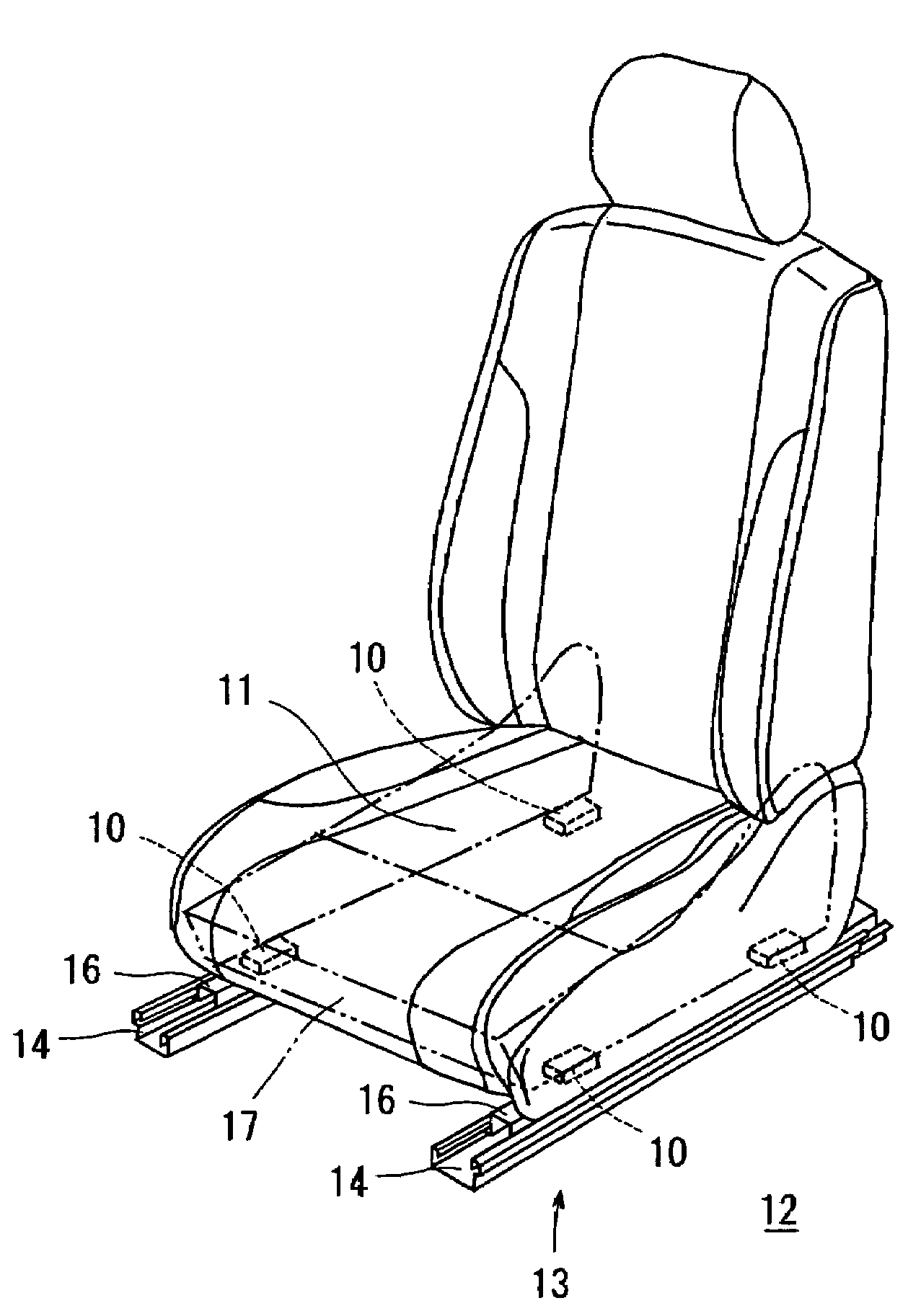
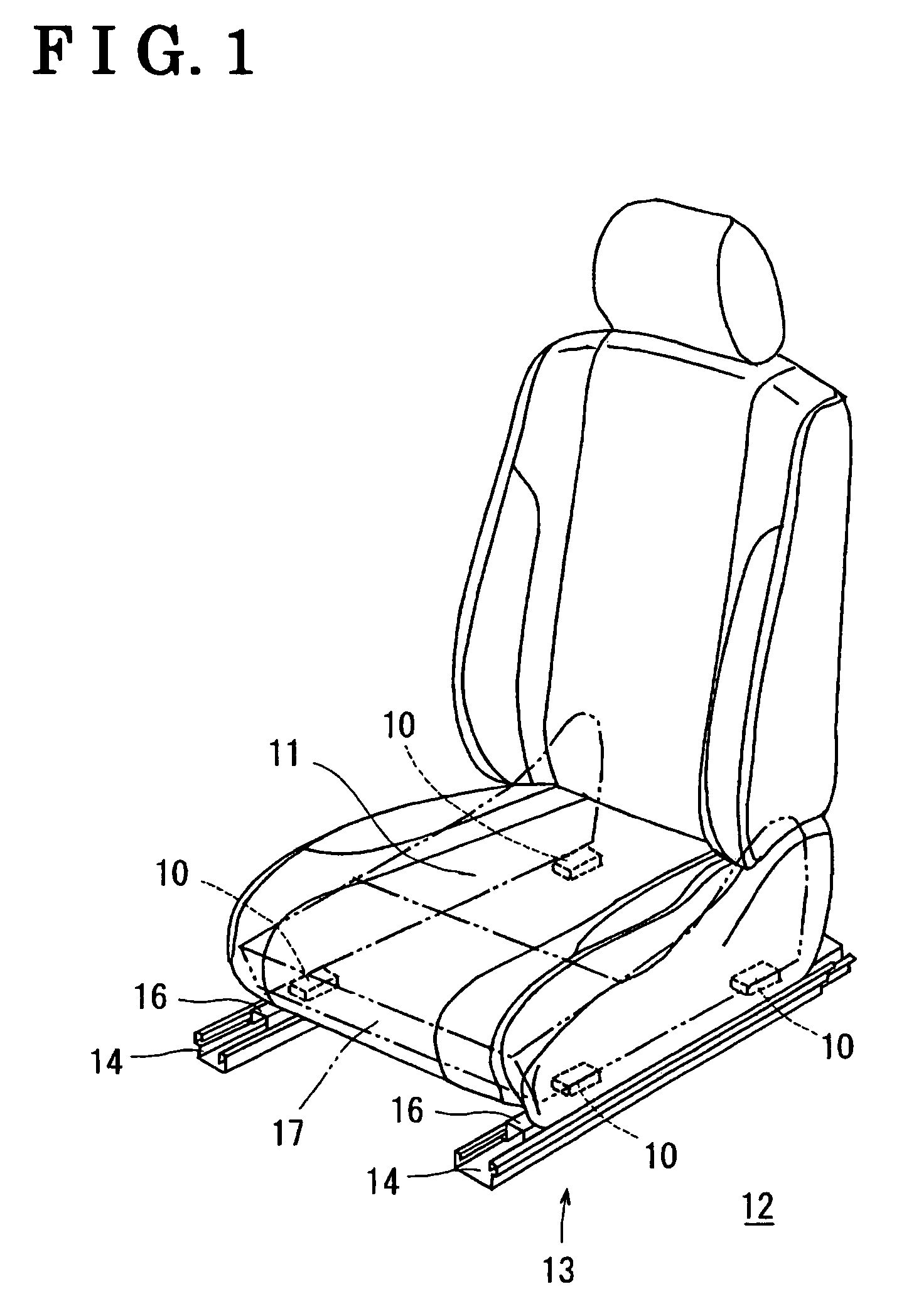
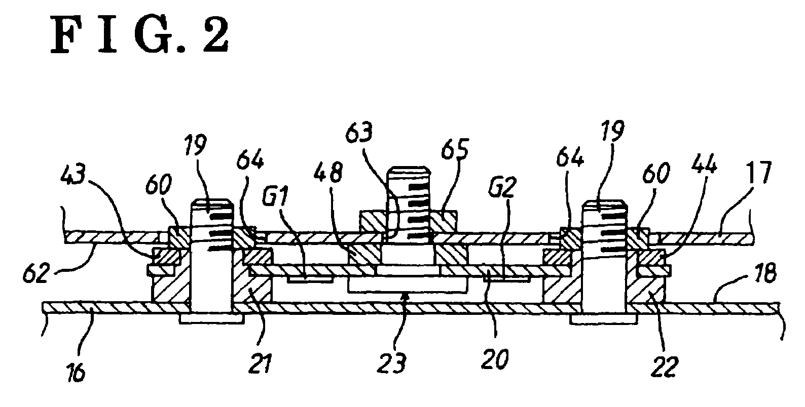
[0018]Described below are occupant load sensors 10 of a vehicle seat 11 according to an embodiment of the present invention, with reference to the attached drawings. The occupant load sensor 10 is configured to measure a load of an occupant seated on the seat 11 illustrated in FIG. 1. A seat sliding apparatus 13 illustrated in FIG. 1 is configured to adjustably secure the seat 11 to a vehicle floor 12. The seat sliding apparatus 13 includes: a pair of lower rails 14 fixedly mounted on the floor 12 and extending in a longitudinal direction of the vehicle; and a pair of upper rails 16 slidably supported by the lower rails 14. A lower portion of the seat 11 is structured with a frame 17 (seat side fixing member) attached to a lower surface of a seat cushion. Among the four corners of the lower surface of the frame 17, two of the corners arranged in the longitudinal direction are fixed to fixing surfaces 18, which are formed at an upper surface of one of the upper rails 16 (floor side f...


PUM


Abstract

An occupant load sensor for a vehicle includes a strain member, a connecting member fixed at the strain member, a strain gauge attached to the strain member, an upper bracket having a fixed portion and an attachment portion connecting each fixed portion and extending at a side of the strain member in a lateral direction of the seat, an amplifier case attached to the attachment portion and arranged in parallel with the strain member, an amplifier substrate enclosed in the amplifier case and placed on an identical plane to the strain member, an FPC substrate connected to the strain gauge and the amplifier substrate, a coating portion for coating a connection portion between the FPC substrate and the strain gauge; and a low pressure molded portion molded with a hot melt resin by low pressure molding in the amplifier case to cover the amplifier substrate and the connection portion.

Description

CROSS REFERENCE TO RELATED APPLICATIONS[0001]This application is based on and claims priority under 35 U.S.C §119 with respect to Japanese Patent Application 2006-296916, filed on Oct. 31, 2006 and Japanese Patent Application 2007-267659, filed on Oct. 15, 2007, the entire content of which is incorporated herein by reference.FIELD OF THE INVENTION[0002]This invention relates to an occupant load sensor measuring a load of an occupant seated on a vehicle seat.BACKGROUND[0003]In JP 2003-83707A, a strain sensor is disclosed. In the strain sensor, an external force is applied to a detecting member pressed into a detecting hole of a sensor substrate (strain member) and a reaction force is applied to first and second fixing members respectively pressed into first and second fixing holes disposed at both sides of the detecting hole. First and fourth strain detecting elements are provided between the detecting hole and the first fixing hole and second and third strain detecting elements are ...

Claims


Application Information

Patent Timeline
Patent Type & Authority Patents(United States)
IPC IPC(8): G01B7/16B60N2/90
CPCB60N2/002G01G19/4142
Inventor NAKANO, SATOHIKOAOYAMA, MUTSUROENOMOTO, AKIRA
Owner AISIN SEIKI KK
Learn More