
Cooling cycle apparatus and method of controlling linear expansion valve of the same

a cooling cycle and linear expansion technology, which is applied in mechanical equipment, refrigeration components, light and heating equipment, etc., can solve the problems of compressors b>1/b>i>a /i>and b>1/b> damaged, the discharge temperature of compressors being excessively increased, and the cooling cycle apparatus not being able to quickly deal with load. , to achieve the effect of improving the reliability of the cooling cycle apparatus, preventing overheating and damag

Inactive Publication Date: 2009-03-31
LG ELECTRONICS INC
View PDF11 Cites 10 Cited by
  • Summary
  • Abstract
  • Description
  • Claims
  • Application Information

AI Technical Summary

Benefits of technology

[0015]Therefore, the present invention has been made in view of the above problems, and it is an object of the present invention to provide a cooling cycle apparatus and a method of controlling a linear expansion valve of the same that is capable of controlling the linear expansion valve based on suction overheat level of the compressors, whereby the cooling cycle apparatus quickly deals with load, and therefore, reliability of the cooling cycle apparatus is improved.
[0019]In accordance with another aspect of the present invention, there is provided a method of controlling a linear expansion valve of a cooling cycle apparatus, wherein an opening level value of the linear expansion valve is controlled based on suction overheat level of compressors of the cooling cycle apparatus.
[0026]As the cooling cycle apparatus according to the present invention comprises: the suction overheat level measuring unit for measuring the suction overheat level of the compressors; the discharge pipe sensor for measuring the discharge temperature of the compressors; and the microcomputer for controlling the linear expansion valve according to the suction overheat level measured by the suction overheat level measuring unit and the discharge temperature measured by the discharge pipe sensor, the linear expansion valve is controlled based on the suction overheat level and the discharge temperature of the compressors. Consequently, the cooling cycle apparatus quickly deals with load, and therefore, reliability of the cooling cycle apparatus is improved.
[0027]The method of controlling the linear expansion valve of the cooling cycle apparatus controls the opening level value of the linear expansion valve based on the discharge temperature of the compressors as well as the suction overheat level of the compressors. Consequently, the present invention has the effect of preventing the discharge temperature of the compressors from being excessively increased, and therefore, preventing the compressors from being overheated and damaged. Furthermore, reliability of the cooling cycle apparatus is improved.
[0028]Also, the method of controlling the linear expansion valve of the cooling cycle apparatus calculates the target opening level value according to the suction overheat level of the compressors to control the liner expansion valve for a predetermined period of time after the compressors are operated, since the discharge temperature of the compressors is relatively low, and calculates the new target opening level value according to the suction overheat level and the discharge temperature of the compressors to control the linear expansion valve a predetermined period of time after the operation of the compressors is initiated. Consequently, the present invention has the effect of optimizing efficiency of the cooling cycle apparatus.

Problems solved by technology

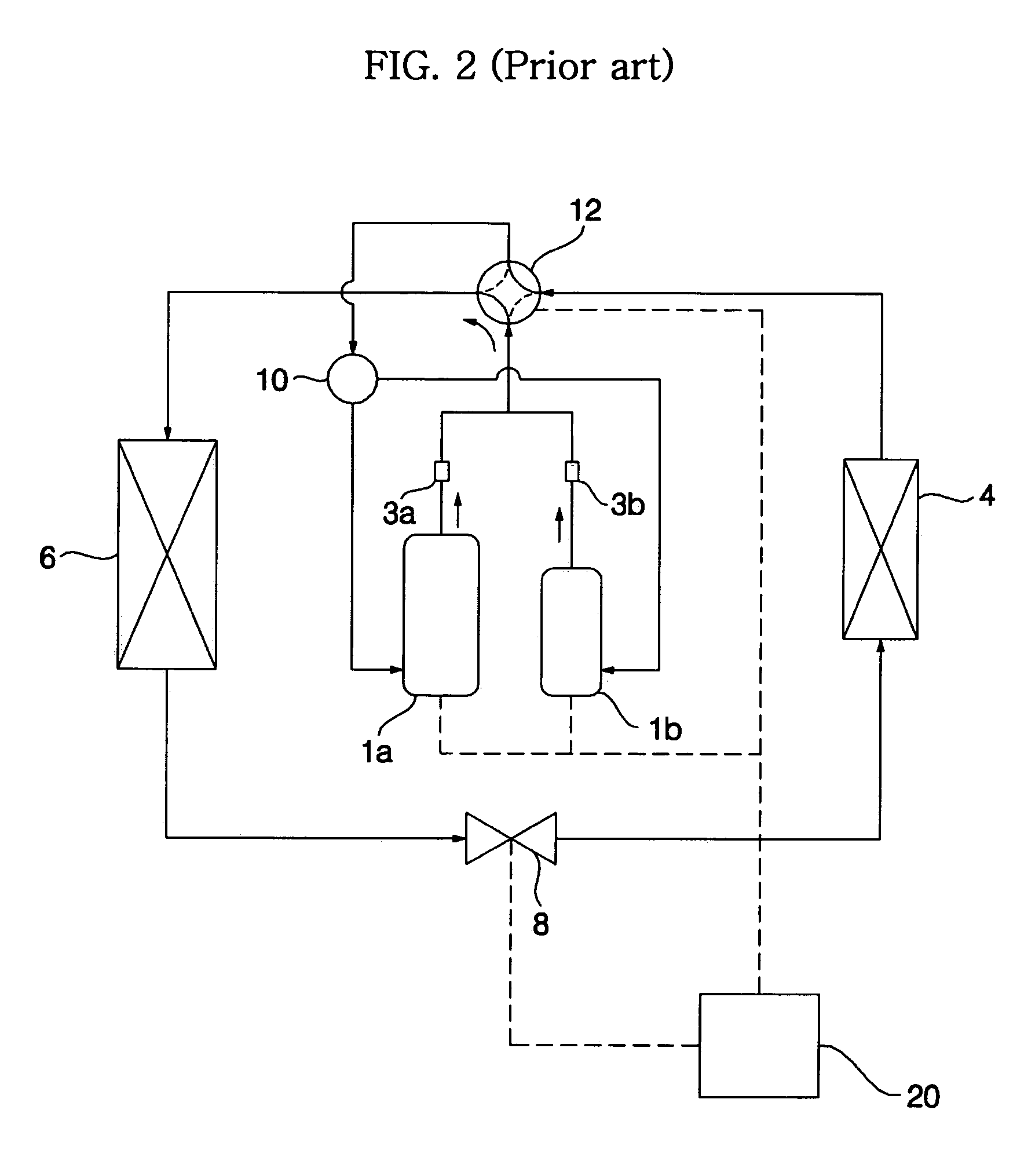
Consequently, when the length of the pipes is increased or the amount of refrigerant is not sufficient, the cooling cycle apparatus does not quickly deal with load.
Furthermore, discharge temperature of the compressors 1a and 1b is increased, and therefore, the compressors 1a and 1b are damaged.

Method used


Image

  • Cooling cycle apparatus and method of controlling linear expansion valve of the same
  • Cooling cycle apparatus and method of controlling linear expansion valve of the same
  • Cooling cycle apparatus and method of controlling linear expansion valve of the same

Examples


Embodiment Construction

[0036]Now, preferred embodiments of the present invention will be described in detail with reference to the accompanying drawings. The same or similar elements are denoted by the same reference numerals even though they are depicted in different drawings, and a detailed description thereof will be omitted.

[0037]FIG. 3 is a circuit diagram showing the flow of refrigerant when a cooling cycle apparatus according to the present invention is operated in cooling operation mode, and FIG. 4 is a circuit diagram showing the flow of refrigerant when the cooling cycle apparatus according to the present invention is operated in heating operation mode.

[0038]As shown in FIGS. 3 and 4, the cooling cycle apparatus according to the present invention comprises: a pair of compressors 51a and 51b for compressing low-temperature and low-pressure gas refrigerant into high-temperature and high-pressure gas refrigerant; an outdoor heat exchanger 54 for performing heat exchange between the refrigerant and ...


PUM


Abstract

Disclosed herein is a method of controlling a linear expansion valve of a cooling cycle apparatus. The method comprises a first step of calculating a target opening level value according to suction overheat level of compressors to control a linear expansion valve based on the calculated target opening level value, and a second step of calculating a new target opening level value according to the suction overheat level of the compressors and discharge temperature of the compressors to control the linear expansion valve based on the calculated new target opening level value. Consequently, the discharge temperature of the compressors is prevented from being excessively increased, and therefore, the compressors are prevented from being overheated and damaged, and reliability of the cooling cycle apparatus is improved.

Description

BACKGROUND OF THE INVENTION[0001]1. Field of the Invention[0002]The present invention relates to a cooling cycle apparatus and a method of controlling a linear expansion valve of the same, and, more particularly, to a cooling cycle apparatus and a method of controlling a linear expansion valve of the same that is capable of controlling the linear expansion valve based on suction overheat level of compressors, whereby the cooling cycle apparatus quickly deals with load, and therefore, reliability of the cooling cycle apparatus is improved.[0003]2. Description of the Related Art[0004]Generally, a cooling cycle apparatus is an apparatus that cools or heats the interior of a room where a specific component of the cooling cycle apparatus is installed. The cooling cycle apparatus comprises a compressor, a condenser, an expansion mechanism, and a vaporizer.[0005]In recent years, a plurality of compressors have been mounted in cooling cycle apparatuses, or a liner compressor whose compressi...

Claims


Application Information

Patent Timeline
Patent Type & Authority Patents(United States)
IPC IPC(8): F25B41/00F25B1/00F25B41/04F25B41/06F25B13/00F25B49/02
CPCF25B13/00F25B49/02F25B2313/0315F25B2400/075F25B2500/06F25B2600/21F25B2600/2513F25B2700/21151F25B2700/21152F25B41/34F25B2341/06
Inventor HWANG, YOON JEIKIM, CHEOL MINCHOI, CHANG MINKANG, SEUNG TAKLIM, HYUNG SOO
Owner LG ELECTRONICS INC
Learn More