Roll-baler

a roll-baler and roller technology, applied in the field of roll-balers, can solve the problems of increasing the complexity of the lock mechanism, the inability to secure the efficient work in the “one-man” controlled operation, and the increase in the cost of manufacturing

Active Publication Date: 2009-03-31
TAKAKITA CO LTD
View PDF22 Cites 17 Cited by
  • Summary
  • Abstract
  • Description
  • Claims
  • Application Information

AI Technical Summary

Benefits of technology

[0013]The present invention has been made with a view to solving the afore-described various problems inherent in the conventional roll-balers, and has as its objective to provide a novel expedient capable of feeding the baler-shaping material of short length, as received in the hopper 2, into the bale chamber 4 through the inlet port “a” of the bale chamber 4 by way of the transporting conveyor 3, while making it possible to secure smooth rotational operations for opening and closing the rear chamber of the bale chamber, and yet with a simple structure of the lock mechanism.
[0015]According to another aspect of the present invention, there is provided an improved roll-baler, which comprises, as set forth in the appended claim 2: a hopper 2, a conveyor 3 for transporting bale shaping material to be discharged from a discharge port 20 of said hopper 2, and a bale chamber 4 for receiving thereinto said bale shaping material conveyed by said transporting conveyor 3 through an inlet port “a” to shape the same into the roll-baler, said component elements being all mounted on a machine body 1, wherein said machine body 1 is formed in a traction-type by providing a connecting rod 10 which projects frontward of the front face side of the machine body, then mounting said hopper 2 to the front face side of said machine body 1, then mounting said transporting conveyor 3 in a manner to rearwardly sending the bale shaping material, and finally mounting said bale chamber 4 to the side of the rear part of said machine body 1 with said inlet port “a” facing the frontward direction; the front wall 2a of said hopper 2 being formed in a separate body with respect to the hopper main body 2b, the lower end part thereof being pivotally supported with a pivotal axis P, to which an actuator 5 is joined, said actuator being mounted on said machine body 1 in a manner to rotate slantendicularly in the front-to-rear direction with the pivotal axis P being made as the center by the actuation of said actuator; then a sliding wall 22, which overlappingly slides with the left and right side walls 21, 21 of said hopper main body 2b, is connected so as to increase and decrease the capacity of said hopper 2 by the rotation of the front wall 2a above said connecting rod 10.

Problems solved by technology

Since the roll-baler A of the configuration, which is not equipped with the abovementioned pick-up device, but accommodates the material of short length for shaping the roll-baler, as cropped and shredded by the harvester, into the hopper 2 is primarily intended for the material of short length for shaping the fodder product, or the like, in its shredded form, it has a problem of being expensive in its manufacture, because, as already mentioned above, since the transporting conveyor 3 is downwardly slanted in the rear direction, and the bale chamber 4 is mounted on the machine body 1 at the position of its receiving port “a” being upwardly slanted in the forward direction, if and when the rear chamber 4b of the bale chamber 4 is caused to be rotated toward the front chamber 4a for its closing, on the center of a pivotal axis S, the closing motion becomes stiff to make it difficult to shut, while its opening motion becomes smooth and easy.
As the consequence, the lock mechanism must be made more intensified or more complicated.
Also, there is another problem such that, since the hopper 2 for receiving the material of short length for the roll-baler shaping is made to have a certain definite volume, if and when the shaping material as harvested by the circular cutting system, at the time of the mouth-opening work, where the fodder product or the like shaping material is harvested by means of the foliage harvester H, is loaded on the bonnet wagon W or the loader bucket B, which is then thrown into the hopper 2 of the roll-baler A at its fixed position, it becomes impossible to charge its total quantity at one time, owing to shortage of the volume capacity of the hopper 2, on account of which the material feeding becomes intermittent or batch-wise to deteriorate the working efficiency.
From what has been described above, there is still other problem such that, unless the roll-baler is attached at the back of the tractor machine body so as to be pulled by it, no efficient work can be secured in the “one-man” controlled operation.
There is still further problem such that a bridging phenomenon is generated within the hopper 2 to make it difficult to feed the shaping material as cropped and shredded into the bale chamber 4 at a certain definite quantity, if and when shaping material, which has been harvested and shredded by the foliage harvester, is thrown into the hopper 2 of the roll-baler A by means of the bonnet wagon, the loader bucket, and so forth, then the shaping material is sequentially discharged from the discharge port 20 of the hopper 2 to be forwarded into the inlet port “a” of the bale chamber 4 through the transporting conveyor 3.

Method used


Image

  • Roll-baler
  • Roll-baler
  • Roll-baler

Examples


Embodiment Construction

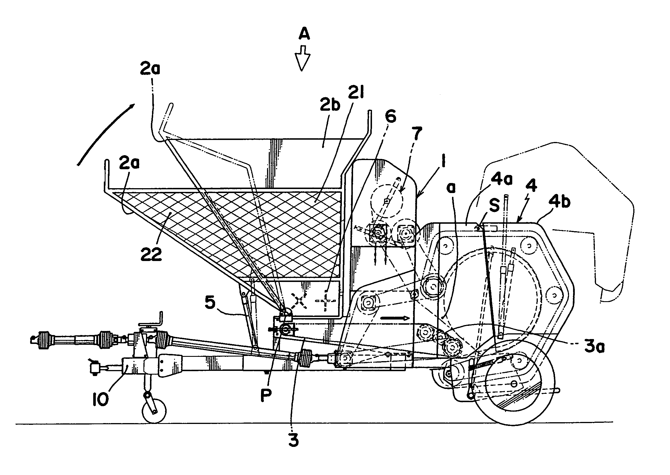
[0032]The roll baler A according to the present invention is constructed with a hopper 2 for receiving therein bale-shaping material of short length; a transporting conveyor 3 for rearwardly sending the bale-shaping material to be discharged from a discharge port 20 defined at the bottom part of the hopper 2; and a bale chamber 4 for receiving the bale-shaping material which is conveyed by the transporting conveyor 3 through a receiving port “a” to be shaped into a roll-bale; all these components being mounted on a machine body 1, wherein the front chamber 4a at the front half side of the bale chamber 4 is fixedly mounted on the machine body 1, while the rear chamber 4b at the rear half side of the bale chamber 4 is pivotally supported on the machine body 1, the hopper 2 being so designed that its content volume may become increased or decreased.

[0033]This increase and decrease of the content volume of the hopper 2 can be expanded or shrinked, as in the embodiment shown in FIGS. 5 t...


PUM

PropertyMeasurementUnit
Lengthaaaaaaaaaa

Abstract

The present invention is concerned with a roll-baler of a construction, in which the rotational movement of its rear chamber of the bale chamber for its opening and closing is done smoothly, while its lock mechanism is designed to be simple, so that the bale-shaping material of a short length may be fed into the bale chamber 4 through its inlet port “a”.In this type of the roll-baler, the bale chamber 4 is mounted on the machine body 1 at its position, where the inlet port “a” of the bale chamber 4 is open frontward, and the terminal end part 3a of the transporting conveyor 3 is so made as to its conveying surface forming an inclined surface “c” which is downwardly slanted, the inclined surface “c” being disposed at a position to constitute a part of the peripheral wall of the bale chamber 4, in opposition to the lower half side of the peripheral surface of the roll bale R to be formed within the bale chamber at the place where the inlet port “a” of the bale chamber 4 is present.

Description

BACKGROUND OF THE INVENTION[0001]a) Field of the Invention[0002]This invention relates to improvement in roll-baler of a type, which conveys materials of short length, such as harvested and shredded farm product for fodder, or the like, into a bale chamber mounted on a machine frame to be shaped and packed into a roll-bale, wherein the machine body is not provided with a pick-up device for picking up the material for shaping such as harvested fodder product, etc., but, instead, there is mounted a hopper for receiving such fodder product to be shaped into the roll-bale, so as to receive into this hopper the fodder materials in short length, which have been harvested and shredded by a foliage harvester, and then the fodder product is gradually taken out of the bottom part of the hopper and fed into the bale chamber by way of a transporting conveyor to be formed into the roll-bale.[0003]b) Description of Prior Arts[0004]FIGS. 1 and 2 of the accompanying drawing in this application illu...

Claims


Application Information

Patent Timeline
IPC IPC(8): B65B11/04A01F15/00A01F15/02A01F15/07A01F15/08A01F15/10
CPCA01F15/07A01F15/085A01F15/106A01F2015/0775A01F2015/078A01F2015/183
Inventor FUKUMORI, KOUICHIMURAKI, AKIRAUEMURA, YUJIOKUMURA, MASANOBUYAMANA, NOBUKISHITO, HIROKATSUSHIBUYA, YUKINORI
Owner TAKAKITA CO LTD
Why Eureka
Try Eureka