Methods and apparatus for using an electrical machine to transport fluids through a pipeline

a technology of electrical machines and pipelines, applied in the direction of positive displacement liquid engines, piston pumps, liquid fuel engines, etc., can solve the problems of adversely affecting the efficiency of the components being used, electric drives may be less efficient than mechanical drives, etc., to facilitate the channeling of a first fluid, facilitate the maintenance of a second fluid, and facilitate heat transfer

Active Publication Date: 2009-03-24
GENERAL ELECTRIC CO
View PDF22 Cites 16 Cited by
  • Summary
  • Abstract
  • Description
  • Claims
  • Application Information

AI Technical Summary

Benefits of technology

[0005]In one aspect, an electrical machine is provided. The machine includes a stator, a rotor magnetically coupled to the stator, and a housing enclosing the rotor and the stator. The housing includes a wall that facilitates channeling a first fluid at a first pressure through a portion of the housing. The machine also includes a stator enclosure defined by at least one wall that facilitates maintaining a second fluid within the stator enclosure. The stator enclosure is positioned within the electric machine housing. The stator enclosure has at least one wall that substantially isolates the second fluid from the first fluid such that only the second fluid is in flow communication with the stator. The stator enclosure has at least one wall that facilitates heat transfer from the second fluid to the first fluid. At least a portion of at least one of the stator enclosure walls is configured to facilitate equalizing the first pressure and the second pressure.
[0007]In a further aspect, a fluid transport station is provided. The station includes a unitary housing including at least one wall. The wall facilitates channeling a first fluid within the unitary housing. The station also includes a fluid transport assembly within the unitary housing. The fluid transport assembly includes at least one rotatable shaft. The station further includes a drive motor positioned within the housing. The drive motor includes a stator with an enclosure and a rotor. The stator enclosure and the rotor are enclosed within the housing. The rotor is magnetically coupled to the stator and the drive motor rotor is rotatably coupled to the fluid transport assembly rotatable shaft. The stator enclosure is defined by at least one wall that facilitates maintaining a second fluid within the stator enclosure. The stator enclosure wall substantially isolates the second fluid from the first fluid such that only the second fluid is in flow communication with the stator. The stator enclosure wall facilitates heat transfer from the second fluid to the first fluid. At least a portion of at least one of the stator enclosure walls is configured to facilitate equalizing the first pressure and the second pressure.

Problems solved by technology

However, systems using electric drives may be less efficient than those systems using mechanical drives.
However, in some cases, the fluid being transported may have aggressive constituents or impurities which may adversely affect the efficiency of the components being used.

Method used


Image

  • Methods and apparatus for using an electrical machine to transport fluids through a pipeline
  • Methods and apparatus for using an electrical machine to transport fluids through a pipeline
  • Methods and apparatus for using an electrical machine to transport fluids through a pipeline

Examples


Embodiment Construction

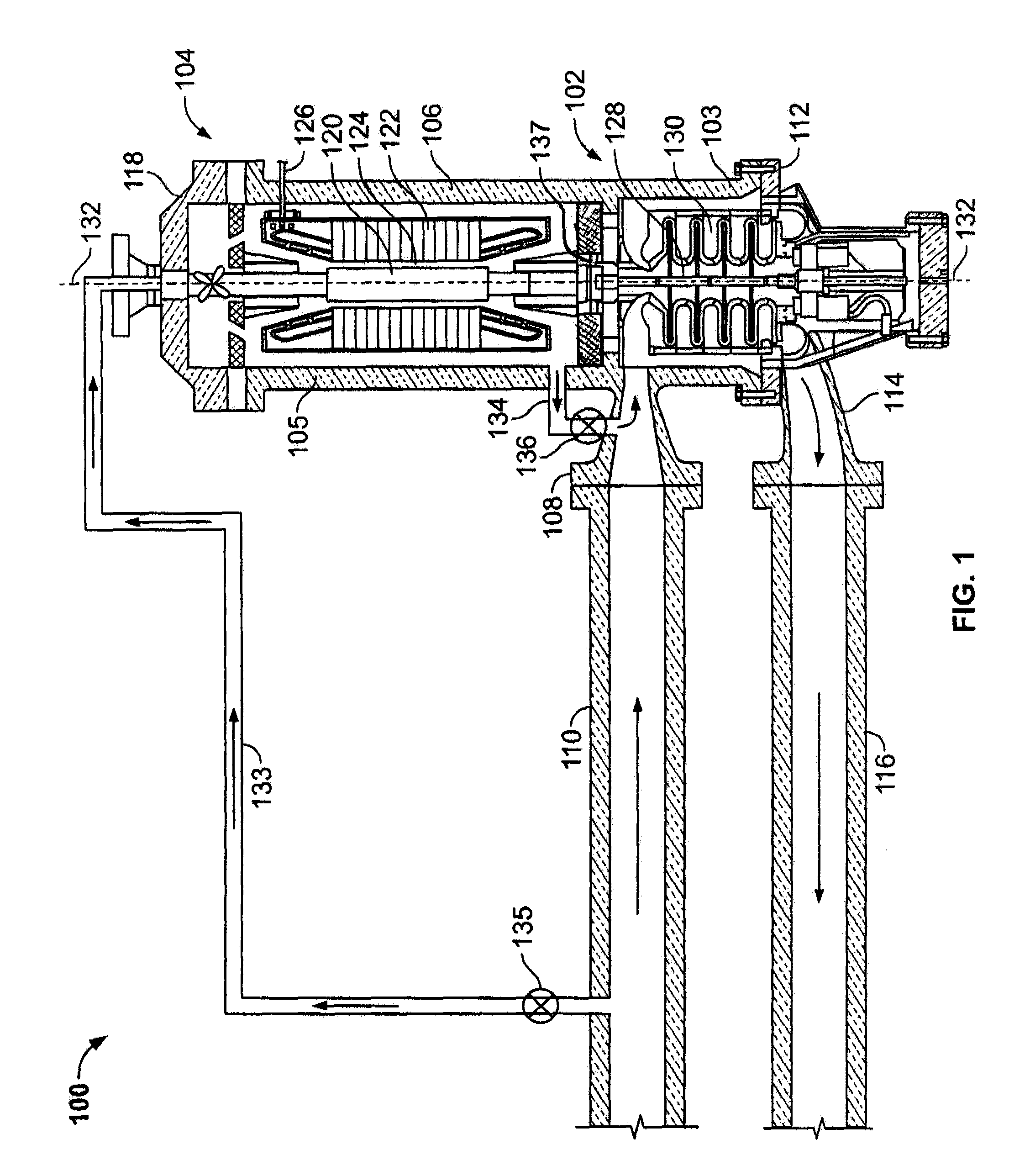
[0012]FIG. 1 is a cross-sectional schematic view of an exemplary fluid transport station 100. In the exemplary embodiment, station 100 is a submerged natural gas compressing station 100 that includes a fluid transport assembly 102. In the exemplary embodiment, assembly 102 is a multi-stage compressor 102 that is rotatingly coupled to an electric drive motor 104. Alternatively, assembly 102 may be, but is not limited to being a pump or a fan. Station 100 may be positioned in any geographical location and may facilitate transport of any fluid wherein predetermined operational parameters are attained. Examples of fluids that may be transported by station 100 include, but are not limited to untreated methane channeled to station 100 from a natural source (not shown in FIG.1).

[0013]In the exemplary embodiment, motor 104 is a permanent magnet-type electric motor 104 designed for operating speeds above the maximum speed of 3600 revolutions per minute typically associated with synchronous m...


PUM


Abstract

An electrical machine to facilitate transporting fluids through a pipeline is provided. The machine includes a stator, a rotor magnetically coupled to the stator, and a housing enclosing the rotor and the stator. The housing includes a wall that facilitates channeling a first fluid at a first pressure through a portion of the housing. The machine also includes a stator enclosure defined by at least one wall that facilitates maintaining a second fluid within the stator enclosure. The stator enclosure is positioned within the electric machine housing. The stator enclosure has at least one wall that substantially isolates the second fluid from the first fluid such that only the second fluid is in flow communication with the stator. The stator enclosure has at least one wall that facilitates heat transfer from the second fluid to the first fluid. At least a portion of at least one of the stator enclosure walls is configured to facilitate equalizing the first pressure and the second pressure.

Description

BACKGROUND OF THE INVENTION[0001]This invention relates generally to fluid transport systems and, more particularly, to methods and apparatus for using an electrical machine to transport fluids through a pipeline.[0002]Fluid transport is used in a variety of different industries including, but not limited to, the chemical, oil and gas industries. In one known fluid transport application fluids are transported from on-shore or off-shore locations to processing plants for subsequent use. In other known applications, fluid transport is used in hydrocarbon processing industries and chemical industries, and to facilitate distribution to end-users.[0003]At least some known fluid transport stations use fluid transport apparatus such as compressors, fans and / or pumps that are driven by gas turbines. Some of these turbines drive the associated fluid transport apparatus via a gearbox that either increases or decreases a gas turbine output drive shaft speed to a predetermined apparatus drive s...

Claims


Application Information

Patent Timeline
Patent Type & Authority Patents(United States)
IPC IPC(8): H02K9/10H02K9/19
CPCF04D1/063F04D29/588H02K9/197F04D13/06F04D17/122F04D25/0606F04D29/5806
Inventor KAMINSKI, CHRISTOPHER ANTHONYWILSON, BLAKE WELDONFOGARTY, JAMES MICHAELJARCZYNSKI, EMIL DONALDGERSTLER, WILLIAM DWIGHTYAGIELSKI, JOHN RUSSELLWEEBER, KONRAD ROMAN
Owner GENERAL ELECTRIC CO
Why Eureka
Try Eureka