
Bagless stick type vacuum cleaner

Inactive Publication Date: 2009-03-24
ROYAL APPLIANCE MFG
View PDF78 Cites 56 Cited by
  • Summary
  • Abstract
  • Description
  • Claims
  • Application Information

AI Technical Summary

Benefits of technology

"The present invention provides a vacuum cleaner with improved dirt separation and filtration capabilities. The vacuum cleaner includes a nozzle base with a main suction opening and a hingedly connected housing with a dirt separation chamber and a dirt receptacle. A conical filter extends into the dirt separation chamber. The vacuum cleaner also includes a suction source and a cyclonic airflow chamber for separating dirt and dust from the suction airstream. A filter assembly is selectively mounted to the cyclonic airflow chamber and includes a longitudinal axis and a support member. The vacuum cleaner further includes a dust cup for holding dirt and dust separated from the suction airstream and a suction source in fluid communication with the dust cup. The present invention provides a vacuum cleaner with improved dirt separation and filtration capabilities."

Problems solved by technology

This design is disadvantageous from the standpoint that two different elements are needed to provide the cyclonic airflow and to filter the dirt from the airstream.

Method used


Image

  • Bagless stick type vacuum cleaner
  • Bagless stick type vacuum cleaner
  • Bagless stick type vacuum cleaner

Examples


Embodiment Construction

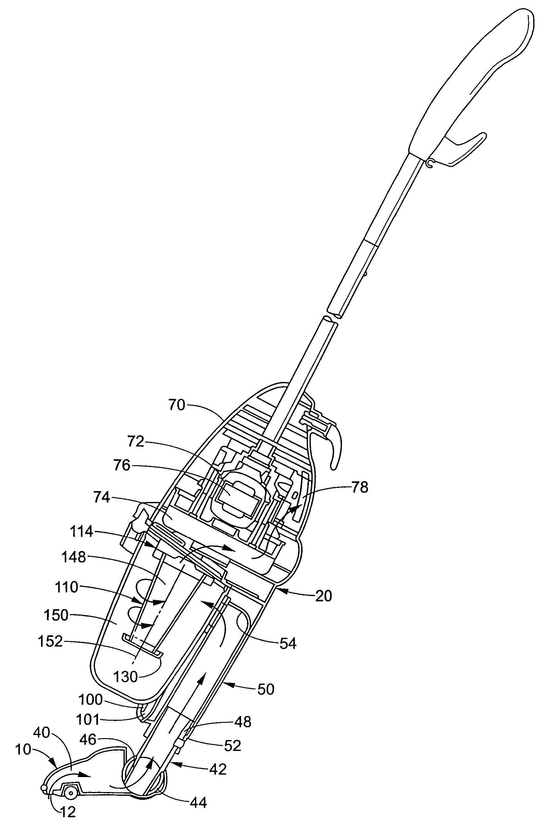
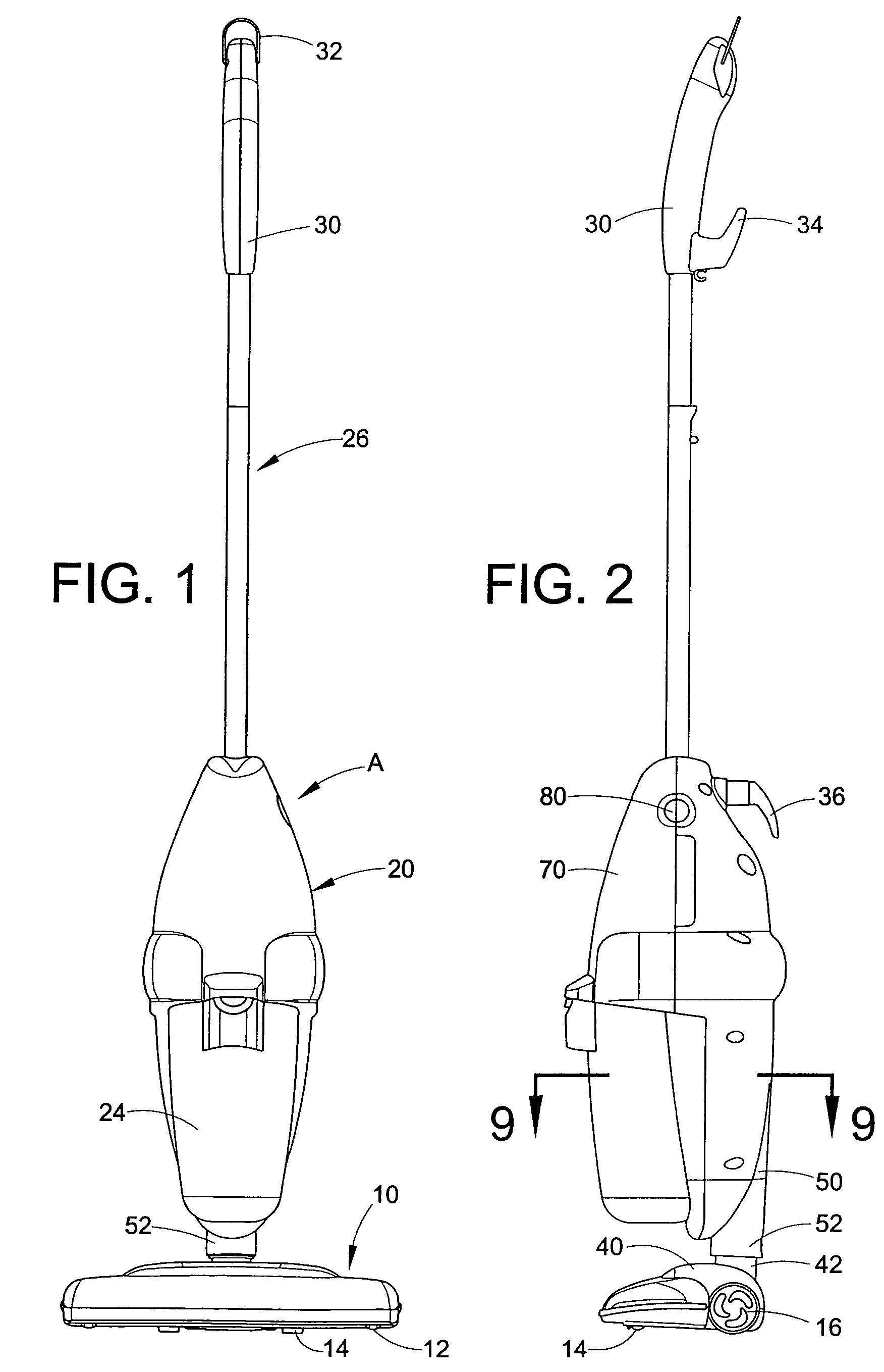
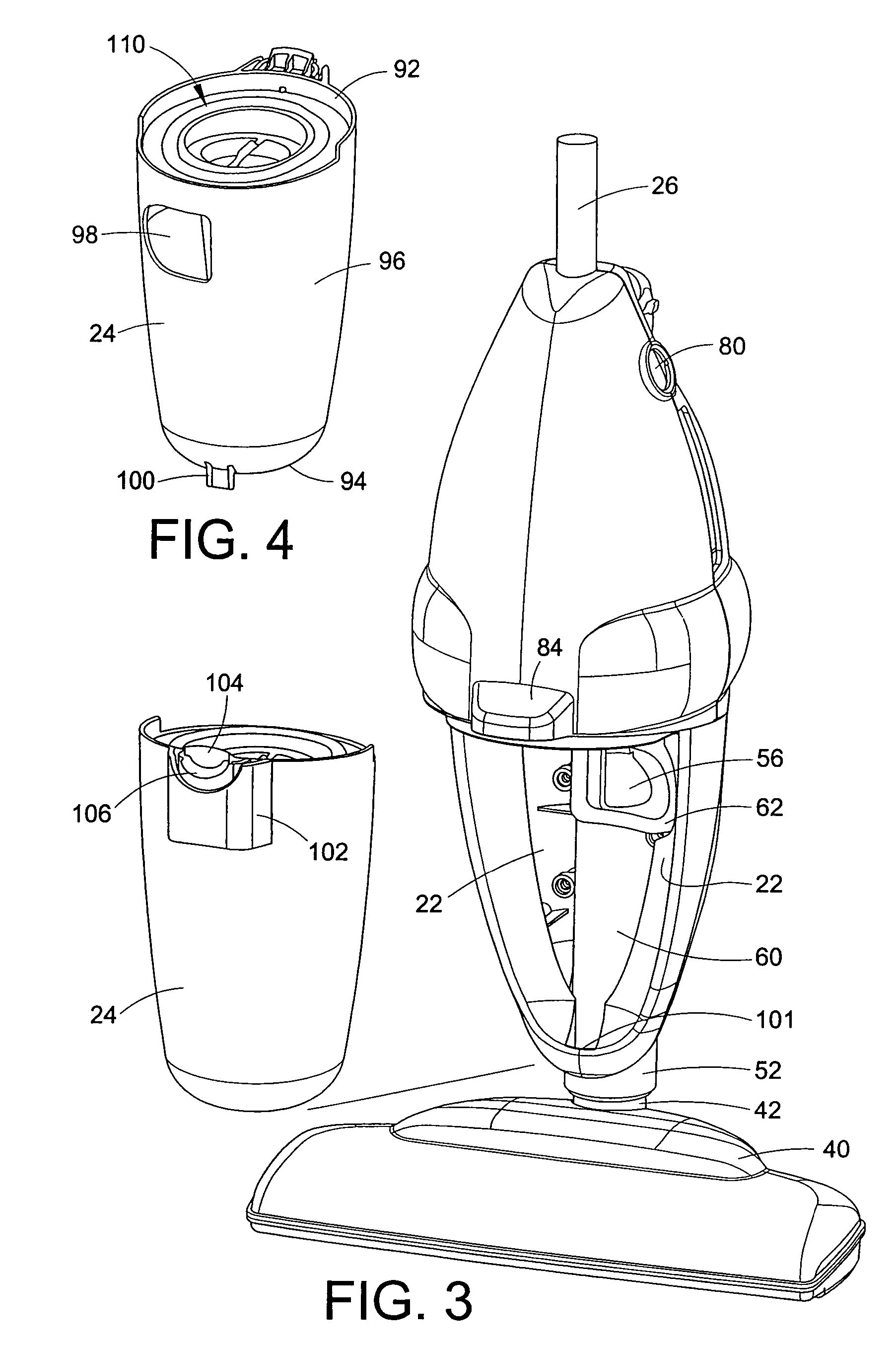
[0026]Referring now to the figures, wherein the showings are for purposes of illustrating several preferred embodiments of the invention only and not for purposes of limiting same, FIG. 1 illustrates a stick vac A including a nozzle base 10 having on an underside thereof a suction opening 12. As best shown in FIG. 10, also provided on the nozzle base are rollers 14, located immediately behind the suction opening, and rear wheels 16. With reference again to FIG. 1, supported on the nozzle base 10 is a housing 20. Defined in the housing is a socket 22 (FIG. 3) for selectively accommodating a dust cup 24. Extending from an upper end of the housing 20 is a handle 26. Positioned on a distal end of the handle is a hand grip 30 which supports a ring 32. The ring can be used to, for example, hang the stick vac from a suitable peg or hook mounted on a wall or in a closet or the like since the stick vac is a relatively light weight appliance.

[0027]With reference now to FIG. 2, also provided o...


PUM

PropertyMeasurementUnit
integral structureaaaaaaaaaa
diameteraaaaaaaaaa
lengthaaaaaaaaaa

Abstract

An upright vacuum cleaner includes a nozzle base having a main suction opening formed in an underside thereof. A housing is hingedly connected to the nozzle base. The housing includes a dirt separation chamber and a dirt receptacle for receiving dirt and dust separated by the dirt separation chamber. A conduit connects the nozzle base to the housing. A suction source is located in one of the housing and the nozzle base. The suction source is in fluid communication with the dirt separation chamber. A generally conically shaped filter extends into the dirt separation chamber along a longitudinal axis of the dirt separation chamber.

Description

[0001]This application is a continuation of U.S. application Ser. No. 10 / 339,829 which was filed on Jan. 10, 2003 and is still pending.BACKGROUND OF THE INVENTION[0002]The present invention relates to vacuum cleaners. More particularly, the present invention relates to stick type vacuum cleaners that employ a dust cup.[0003]Upright vacuum cleaners are very well known in the art. One type of upright vacuum cleaner which has become common in the marketplace is a stick type vacuum cleaner in which a dust cup is employed for holding dirt and dust separated from an airstream. In most stick type vacuum cleaners, a nozzle base travels across a bare floor, carpet or other surface being cleaned. Pivotally mounted to a nozzle base is an upright housing portion. Often this is formed as a rigid plastic housing having a socket for accommodating the dust cup. As is well known, a suction source such as a motor and fan assembly is mounted to either the nozzle base or the upright housing of the vacu...

Claims


Application Information

Patent Timeline
Patent Type & Authority Patents(United States)
IPC IPC(8): B01D47/02A47L9/16A47L9/24A47L5/28A47L9/12
CPCA47L5/28A47L9/127A47L9/165A47L9/1666Y10S55/03
Inventor MURPHY, JOHN S.KHALIL, DAVIDWRIGHT, MICHAEL F.MATOUSEK, ROBERT A.HIN, YUNG LEONG
Owner ROYAL APPLIANCE MFG
Learn More