Apparatus and method for ink jet printing

a technology of ink jet printing and nozzles, applied in the direction of printing, inking apparatus, other printing apparatus, etc., can solve the problems of uneven density of formed images, degrade image quality, and difficult to densely arrange a large number of nozzles in a single substrate in a line, so as to reduce density unevenness

Inactive Publication Date: 2009-03-24
CANON KK
View PDF4 Cites 7 Cited by
  • Summary
  • Abstract
  • Description
  • Claims
  • Application Information

AI Technical Summary

Benefits of technology

[0023]An object of the present invention is to provide an apparatus and method for ink jet printing which can reduce density unevenness caused by an end deviation condition associated with ink droplets ejected from a print head, regardless of gray scale of a printed image.
[0027]According to the present invention, even if end deviation occurs at the end of the nozzle array, the print duty for the nozzle located at the end of the nozzle array is set on the basis of the amount of the end deviation. The present invention can thus reduce the density unevenness in images regardless of the end deviation amount.

Problems solved by technology

In the manufacture of long print heads such as those used in the full line type ink jet printing apparatus, it is technically and economically difficult to densely arrange a large number of nozzles in a single substrate in a line.
However, in this connecting head, the end deviation occurs in each chip, making the density of a formed image uneven.
These white stripes degrade image quality.
However, low-print-rate printing executed by each chip reduces the end deviation amount, possibly making the dot spacing smaller than the appropriate one, in contrast to high-print-rate printing.
This degrades image quality.
It is thus difficult for the full line type ink jet printing apparatus to reduce density unevenness caused by the end deviation condition in the chips.
This degrades image quality.
However, this technique cannot correct a variation in ejection amount among the nozzles of the print head.
In particular, the application of this technique to the serial type ink jet printing apparatus disadvantageously results in density unevenness at each connecting portion between images formed by the respective scans.
Thus, the correction based on a pattern of a fixed density as described above does not enable the density unevenness to be sufficiently corrected.
Consequently, the HS method requires a large number of correction tables that correct the density unevenness over the entire density area covering all densities from low density to high density.
Providing these correction tables is difficult.
Thus, none of the conventional techniques sufficiently eliminate possible density unevenness on images.
In particular, when pictorial color images or the like are printed on the basis of image signals (multivalue data) input by an external instrument via a read device or the like, density unevenness may occur.
For example, if a full color image composed of four colors, cyan, magenta, yellow, and black, is printed by the serial type ink jet printing apparatus using a small number of passes, density unevenness may occur at the connecting portions between images printed by the respective scans.
With the full line type ink jet printing apparatus, density unevenness may occur frequently at the connecting portions between images formed by the respective chips.
The change in hue may result in color unevenness in images or degraded image color reproducibility (increased color difference).
This degrades image quality.
However, this increases the number of scans executed by the print head, significantly reducing print speed.

Method used


Image

  • Apparatus and method for ink jet printing
  • Apparatus and method for ink jet printing
  • Apparatus and method for ink jet printing

Examples


first embodiment

[0048]First, with reference to FIGS. 13 and 14, description will be given of an example of basic configuration of an ink jet printing apparatus applied to the embodiment of the present invention.

[0049]FIG. 13 is a perspective view schematically showing an example of configuration of a mechanism section of a full line type ink jet printing apparatus applied to the embodiment of the present invention.

[0050]The full line type ink jet printing apparatus 60 in the present example prints an image on a print sheet S as a print medium by ejecting ink from nozzles in a print head 10 provided at a given position while conveying the print sheet S on a conveying belt 61. The long print head 10 extends over a width larger than that of print sheets S of an applicable maximum size. The print head 10 enables an image to be continuously printed by ejecting ink droplets onto the print sheet S being continuously conveyed. In the present example, the print head 10 includes a print head 10Y that ejects ...

second embodiment

[0079]Now, a second embodiment of the present invention will be described.

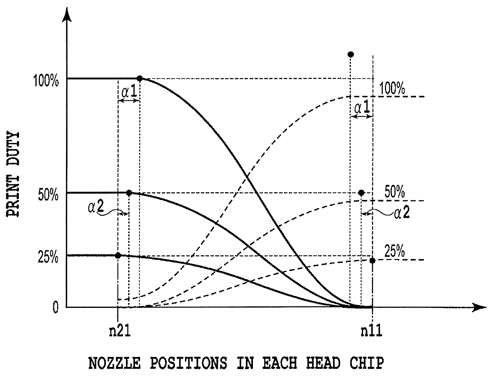
[0080]With ink jet printing apparatuses, ink droplets land on the print sheet S land on a rectangular enclosed pixel area virtually set on the print sheet S. At this time, the ink droplets landed on the print medium bleed and protrude from pixel area to form round dots. In this case, at a lower print duty, a smaller number of dots are placed on the print sheet S, allowing the optical density to be easily increased. However, at a higher print duty, adjacent dots overlap each other, suppressing an increase in optical density. To correct this, the gamma correction process is normally executed for the density value expressed by the original image data so as to reduce the density value of an image formed on the print sheet S. The second embodiment executes an integrated correction composed of this gamma correction integrated with the end deviation correction (see FIG. 6B).

[0081]Thus, compared to the end deviation c...

third embodiment

[0083]Now, a third embodiment of the present embodiment will be described with reference to FIGS. 7 and 8.

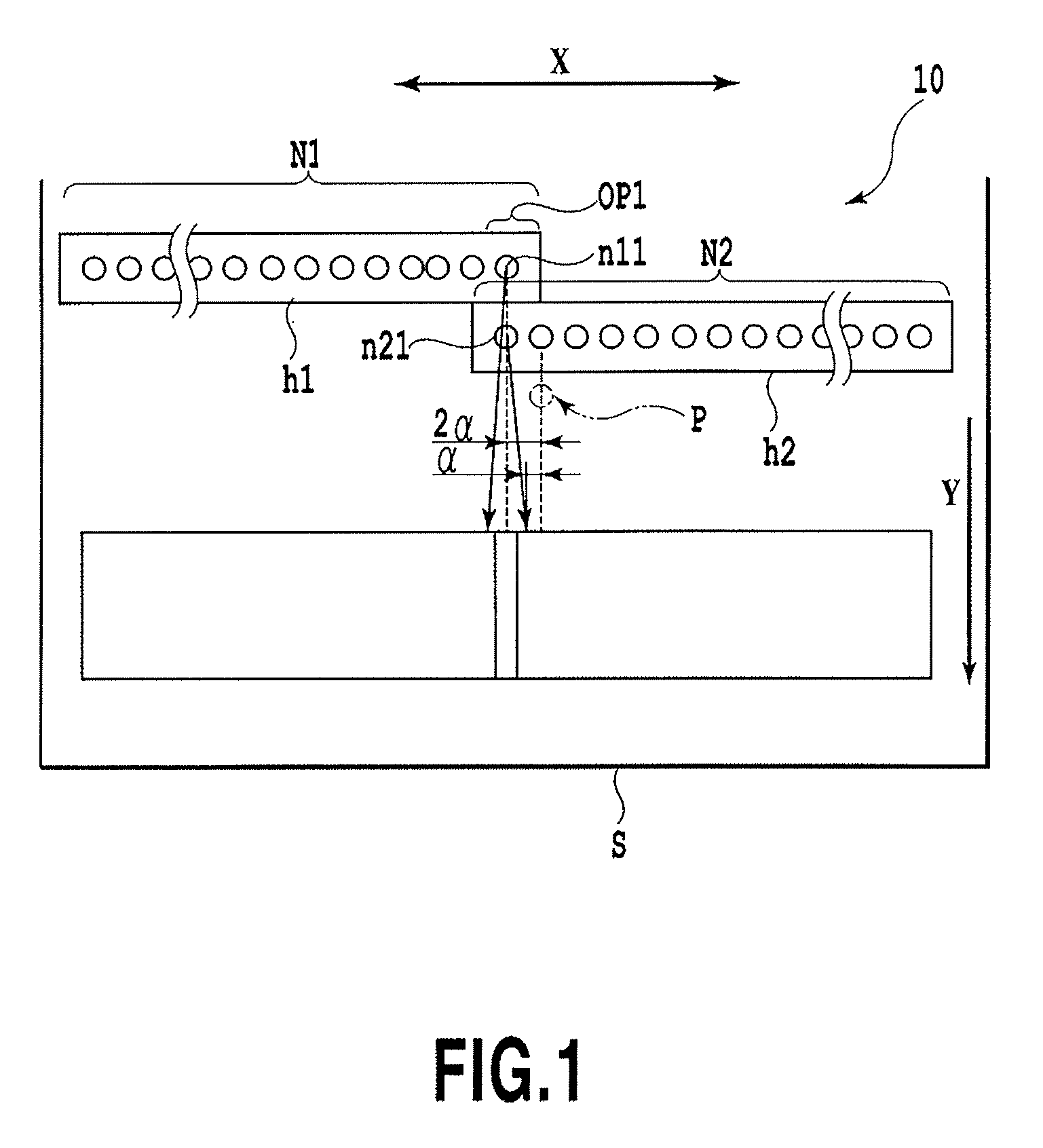
[0084]In the description of the example for the first and second embodiments, the total distance (2α) corresponding to the maximum end deviation amounts of the terminal nozzles in the head chips h1 and h2 is equal to the distance between the terminal nozzle n21 in the head chip h2 and the reference position P. In contrast, in the print head 10 according to the third embodiment, as shown in FIG. 7, the head chip h2 is placed so that the distance T between the terminal nozzle n21 in the head chip h2 and the reference position P is more than double the maximum end deviation amount (α). In FIG. 7, OP2 denotes the connecting portion between the head chips h1 and h2.

[0085]This makes it possible to suppress a rapid change in the density of an image formed by the connecting portion OP2. Thus, an image formed by the connecting portion OP2 and images formed by other portions can be smooth...


PUM


Abstract

An apparatus and method for ink jet printing can reduce density unevenness caused by an end deviation condition associated with ink droplets ejected from a print head, regardless of gray scale of a printed image. The present invention thus sets the print duty for a nozzle located at an end of a nozzle array formed in a print head on the basis of the end deviation amount of a position impacted by an ink droplet ejected from the end of the nozzle array.

Description

BACKGROUND OF THE INVENTION[0001]1. Field of the Invention[0002]The present invention relates to an apparatus and method for ink jet printing which executes printing by executing a scanning relative to a print medium using a print head, the print head having a nozzle array in which a plurality of ink ejecting nozzles are disposed.[0003]2. Description of the Related Art[0004]Various forms of printing apparatuses have been proposed or implemented which execute printing on print media such as paper or OHP sheets; these printing apparatuses are classified by a printing scheme for a print head. Print heads are based on a wire dot scheme, a thermal scheme, a thermal transfer scheme, or an ink jet scheme. Among these printing apparatuses, ink jet printing apparatuses have been gathering much attention; the ink jet printing apparatus uses a print head based on the ink jet scheme to jet ink directly onto print media, and thus requires reduced running costs and is very silent.[0005]The ink je...

Claims


Application Information

Patent Timeline
Patent Type & Authority Patents(United States)
IPC IPC(8): B41J29/38
CPCB41J2/04508B41J2/0458B41J2/04581B41J2/155B41J2/2132B41J2202/20
Inventor TSUBOI, HITOSHIKOITABASHI, NORIBUMI
Owner CANON KK
Why Eureka
Try Eureka