
Heating rack

a rack and heat technology, applied in the field of heat racks, can solve the problems personal danger to users, fat running down and dripping into heated coals and ignites, etc., and achieve the effect of reducing the risk of molten liquid dropping on to hot surfaces or heating surfaces

Inactive Publication Date: 2009-03-24
WORTON IAN GEOFFREY +1
View PDF28 Cites 5 Cited by
  • Summary
  • Abstract
  • Description
  • Claims
  • Application Information

AI Technical Summary

Benefits of technology

[0009]An object of the present invention is to provide a heating rack suitable for use in barbecues, on open fires, in cooking ovens or in heating furnaces that reduces the risk of molten liquids dropping on to hot surfaces or heating surfaces.
[0010]A particular object with regards to cooking of foods over hot charcoal, coals, synthetic coals and ceramics, or naked flames is to reduce the risk of juices and melted fats from dropping on to the heat source and thereby causing flare ups or increased smoke whilst at the same time exposing more of the food to direct radiated or convected heat from the heat source.
[0012]Beneficially, the vertical heat radiation is optimised, thereby to improve cooking efficiency.
[0013]Optionally, each elongate member is spaced from an adjacent elongate member by a distance in the range of 5 mm to around 15 mm, thereby to induce flow of exudates by surface tension effect. In some embodiments the vertical distance between the contact surface and the proximal end of the lateral portion is about 1 mm or more, thereby to encourage flow of exudates into the channel by a surface tension effect.

Problems solved by technology

One of the main problems with cooking fatty foods such as sausages, meat, kebabs, beef burgers and the like over charcoal or gas heated synthetic charcoal or coals, is that the fat runs down and drips into the heated coals and ignites.
This causes flames to rise and overcook or burn the food being cooked.
Often the resulting flare-up causes personal danger to the user and many a user of barbecues have barbecued more than they bargained for!
There have been a number of attempts, some very complex solutions, to prevent the fat from igniting.
One problem associated with the prior art is that those solutions have resulted in a reduction of direct heat radiation from the heat source, which is undesirable because it reduces the cooking efficiency.

Method used


Image

  • Heating rack
  • Heating rack
  • Heating rack

Examples


Embodiment Construction

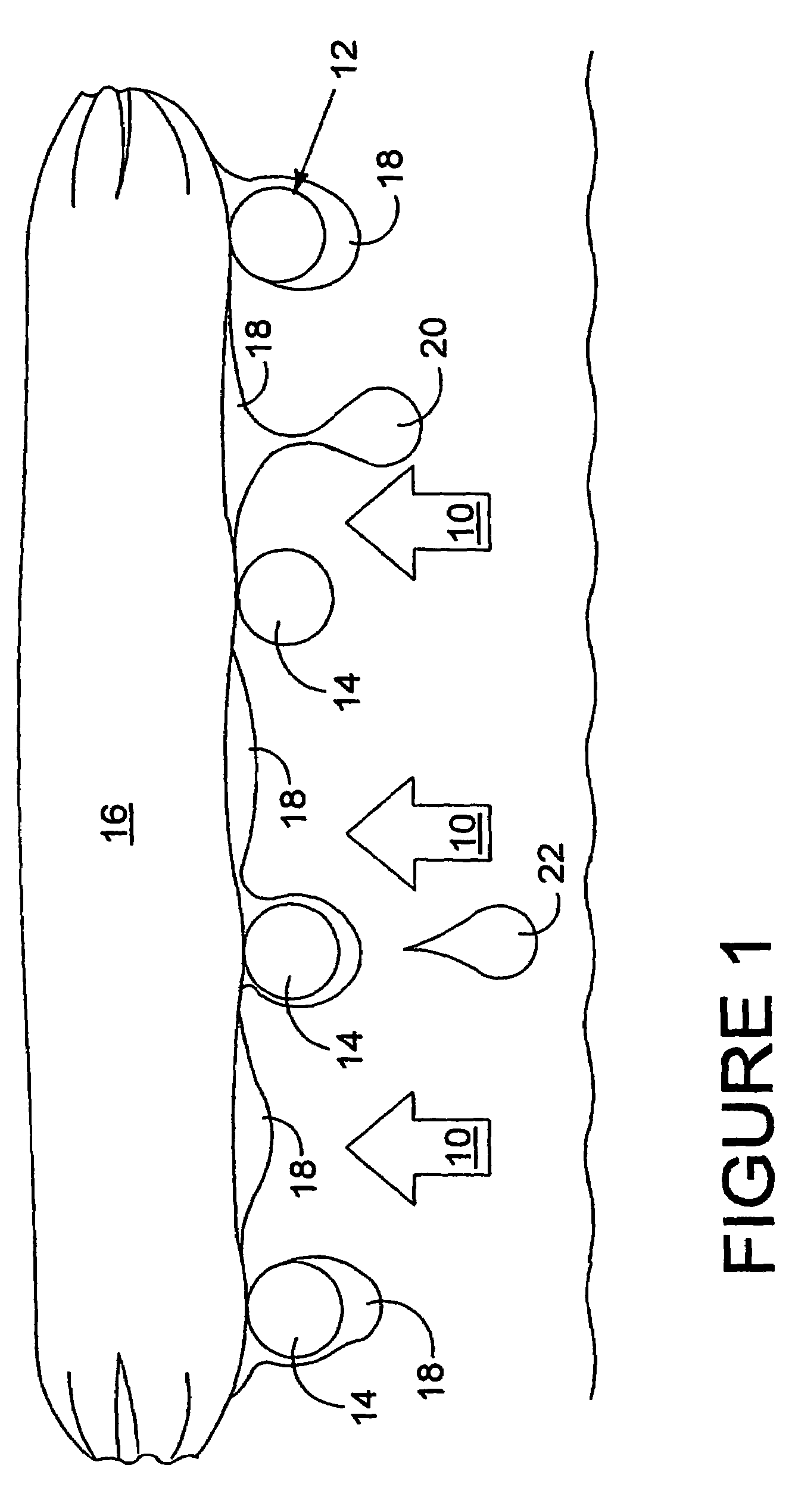
[0030]Referring to FIG. 1 a known barbecue comprises a source of heat 10 which may be a naked flame, hot glowing charcoal, coke or coal, or synthetic heated “coals” made of ceramics, cement, or porous volcanic rocks heated by gas flames. A rack 12 is positioned above the heat source 10 on which food to be cooked is placed. The rack 12 comprises a plurality of rack members in the form of spaced elongate bars 14 of circular cross-sectional shape. Conventionally the bars 14 are welded to a supporting frame (not shown) that extend transverse to the lengths of the bars 14.

[0031]FIG. 1 shows a sausage 16 that is heated by the heat source 10 to a temperature at which the fat 18 starts to melt and run along the underside of the sausage. The fat 18 builds up to a droplet 20 that falls onto the heat source 10 and ignites. Some of the melted fat 18 runs along the underside of the sausage until it touches the bars 14. The melted fat then builds up around the bars and drips off the underside of ...


PUM


Abstract

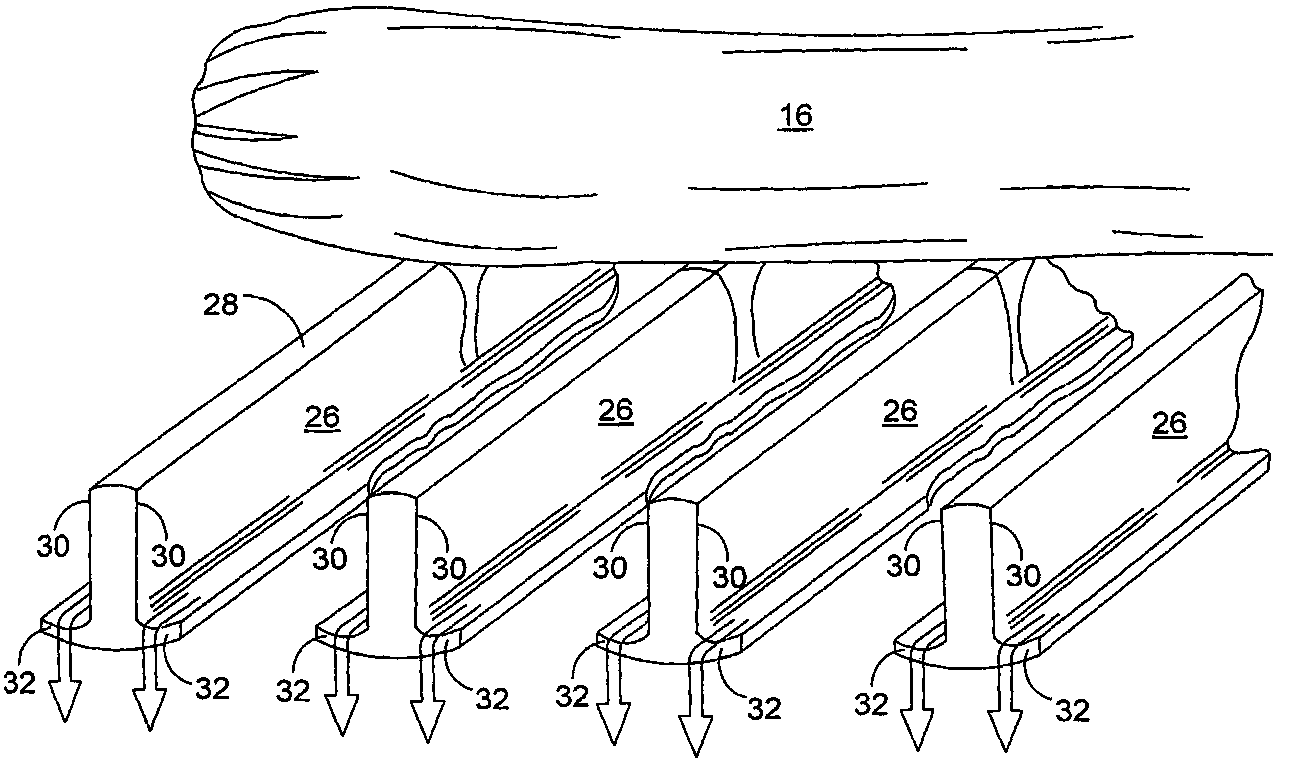
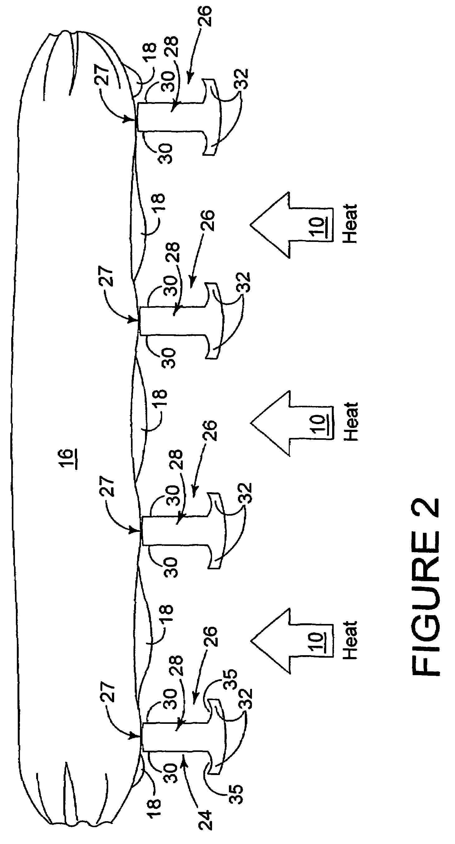
A heating rack comprising a plurality of spaced discrete elongate members (26) which an object (16) to be heated is placed and exposed to a source of heat. Each member (26) having a main body (28) with two side faces (30) that, in use, extend in a vertical direction and along the member (26), and a side member (32) located at the lowermost extremity of each side face (30). Each side member is shaped, positioned, and arranged, relative to its respective side face (30) so that, in use, liquid from the object (16) when it is heated is induced to run down each side face (30) due to surface tension effects and is collected by each side member (32) and directed in a direction along each side member (32) to a collection region at one or both ends of the members (26).

Description

BACKGROUND OF THE INVENTION[0001]1. Field of the Invention[0002]This invention relates to heating racks and in particular, although not exclusively to heating racks for heating and cooking food. The invention has particular relevance to the cooking of fatty foods over naked flames such as barbecues.[0003]2. Description of the Related Art[0004]It is to be understood that the present invention may be applied in cooking ovens or in grills and industrial ovens. Where the context permits, the present invention may be used in the heating of other objects where heating the object results in the melting of the object.[0005]One of the main problems with cooking fatty foods such as sausages, meat, kebabs, beef burgers and the like over charcoal or gas heated synthetic charcoal or coals, is that the fat runs down and drips into the heated coals and ignites. This causes flames to rise and overcook or burn the food being cooked.[0006]Often the resulting flare-up causes personal danger to the use...

Claims


Application Information

Patent Timeline
IPC IPC(8): A47J37/06A47J37/07
CPCA47J37/0694A47J37/0704A47J37/07
Inventor WORTON, IAN GEOFFREYNEATH, PETER KARL
Owner WORTON IAN GEOFFREY
Learn More