
Object-relational model based user interfaces

a technology of relational model and user interface, applied in the field of object-relational model-based user interface, can solve the problems of complex tasks, utility differences from application to application, and insufficient rich interaction between objects in the system, so as to facilitate the extension of components

Inactive Publication Date: 2009-03-17
MICROSOFT TECH LICENSING LLC
View PDF25 Cites 17 Cited by
  • Summary
  • Abstract
  • Description
  • Claims
  • Application Information

AI Technical Summary

Benefits of technology

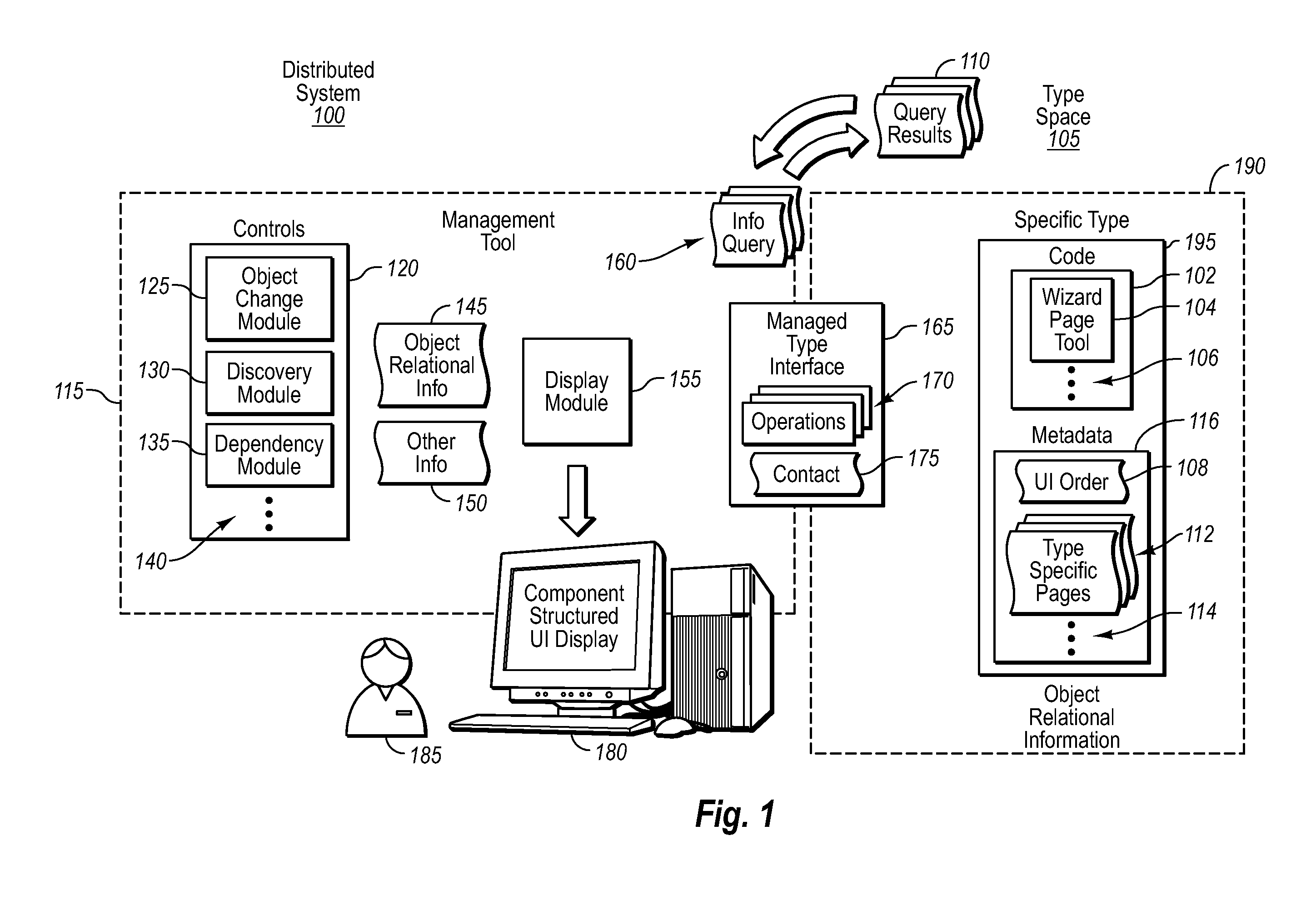
The present invention provides a management tool for distributed systems that overcomes the deficiencies and drawbacks of current tools. The tool is based on an object-relational model and allows for easy extension of components. It dynamically generates a user interface based on the received object-relational information and does not require the general framework to have encoded specific knowledge of the types, relationships, and what should be displayed. The invention allows for better management and control of objects within a distributed system.

Problems solved by technology

From an administrative standpoint, such tasks can become quite complex depending on the skill set of the administrator, the complexity of the system, and other factors.
Often, however, these utilities differ from application to application—mostly in terms of size, complexity, and functionality.
In addition, as the complexity of hardware and / or software grows, richer interaction between objects in the system is needed.

Method used


Image

  • Object-relational model based user interfaces
  • Object-relational model based user interfaces
  • Object-relational model based user interfaces

Examples


Embodiment Construction

[0020]The present invention extends to methods, systems, and computer program products for dynamically generating object-relational model based user interface (UI) for a management tool. The embodiments of the present invention may comprise a special purpose or general-purpose computer including various computer hardware or modules, as discussed in greater detail below.

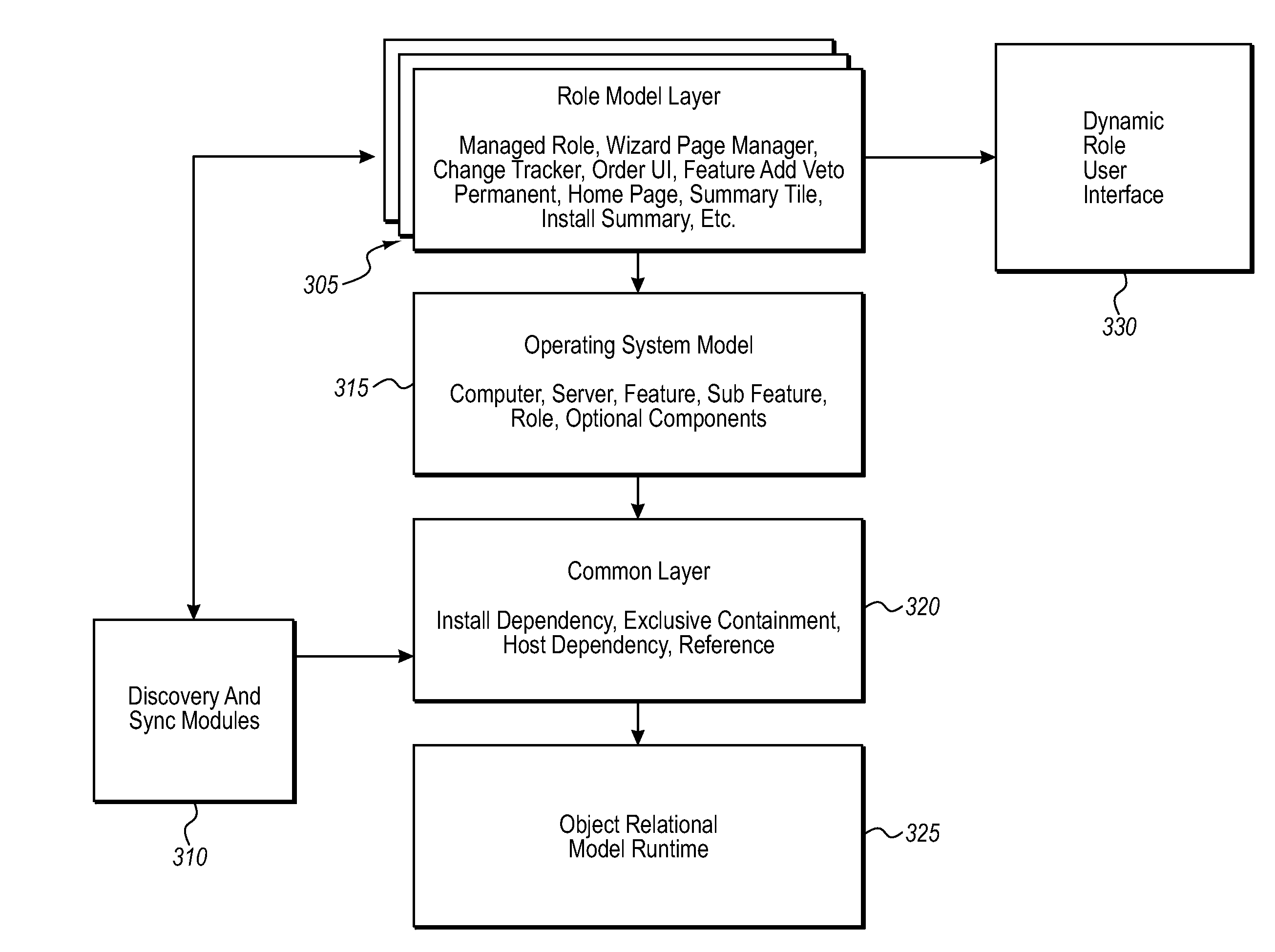
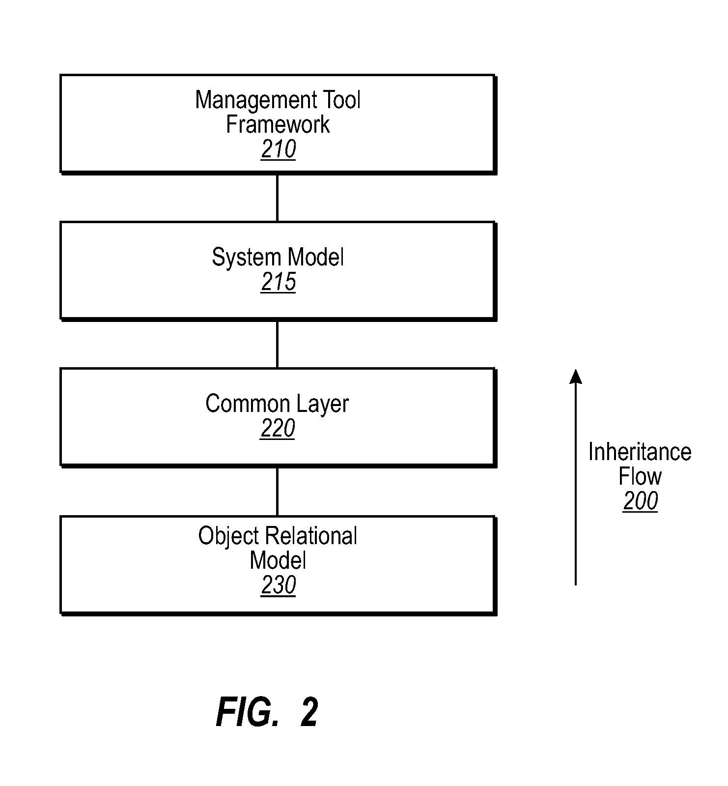
[0021]Embodiments herein provide for a dynamically generated UI management tool for controlling objects within a distributed system. The general framework is part of a hierarchical, layered system built on top of an object-relational model (e.g., System Definition Model (SDM)), which is implemented in a runtime that provides a type space containing types for relationships and objects. The runtime further includes an instance space that comprises individual instantiations of those types. The management tool infrastructure built on top of this object-relational model runtime provides both common model types for system m...


PUM


Abstract

Embodiments provide for a dynamically generated UI management tool, which is part of a hierarchical, layered system built on top of an object-relational model. It provides both common model types for system modeling, as well as transaction engines. The transaction engines allow for such things as discovery of objects within a live system into an instant space and synchronization of the instant space back to the live system, which may then be used when committing requested changes to objects. Upon gathering of object-relational information within the system, the UI can be dynamically generated showing derived relationships between objects, settings, parts, or attributes for the system, without requiring the general framework to have specific knowledge of the types, relationships, and what should be displayed. As such, a change to the specific types does not require a change to the general framework.

Description

CROSS-REFERENCE TO RELATED APPLICATIONS[0001]N / ABACKGROUND[0002]Although computers were once isolated and had minimal or little interaction with other computers, today's computers interact with a wide variety of other computers through Local Area Networks (LANs), Wide Area Networks (WANs), dial-up connections, and so forth. With the wide-spread growth of the Internet, connectivity between computers is becoming more important and has opened up many new applications and technologies. The growth of large-scale networks, and the wide-spread availability of low-cost personal computers, has fundamentally changed the way that many people work, interact, communicate, and play.[0003]Using similar communication networks as those described above, distributed systems provide a decentralized and parallel computing combination of hardware and / or software resources that communicate to accomplish a common objective or task. The types of hardware, programming languages, operating systems, and other ...

Claims


Application Information

Patent Timeline
Patent Type & Authority Patents(United States)
IPC IPC(8): G06F17/30
CPCH04L41/0233H04L41/08H04L41/22Y10S707/99944Y10S707/99943
Inventor GREALISH, KEVIN D. J.GUSTIN, REID B.
Owner MICROSOFT TECH LICENSING LLC
Learn More