
Programming automation by demonstration

a technology of programming automation and demonstration, applied in the field of computer-controlled automation, can solve the problems of affecting the performance of the inability to create or modify control programs, and the inability to achieve the entire conventional approach to programming automation, etc., and achieve the effect of facilitating and facilitating economic performan

Inactive Publication Date: 2009-03-17
SIEMENS CORP
View PDF15 Cites 59 Cited by
  • Summary
  • Abstract
  • Description
  • Claims
  • Application Information

AI Technical Summary

Benefits of technology

[0013]The present invention advantageously provides programming automation by demonstration by using one tool that combines the control programming and the user interface programming. Using programming by demonstration techniques, computer-controlled automation can be performed more easily and economically, without the need for multiple specialists having different areas of particular expertise.

Problems solved by technology

The main challenge to the control programmer is to transform the desired operation and sequencing of the physical machines into appropriate instructions for the PLC.
As such, constructing the control and visualization software for automation applications is often a time-consuming and expensive undertaking.
However, conventional user interface systems are not designed for creating or modifying control programs.
Accordingly, it is seen that the entire conventional approach in automation to programming, including the first and second programming tasks discussed above, that uses current conventional programming languages has a major disadvantage of being expensive and time consuming.

Method used


Image

  • Programming automation by demonstration
  • Programming automation by demonstration
  • Programming automation by demonstration

Examples


Embodiment Construction

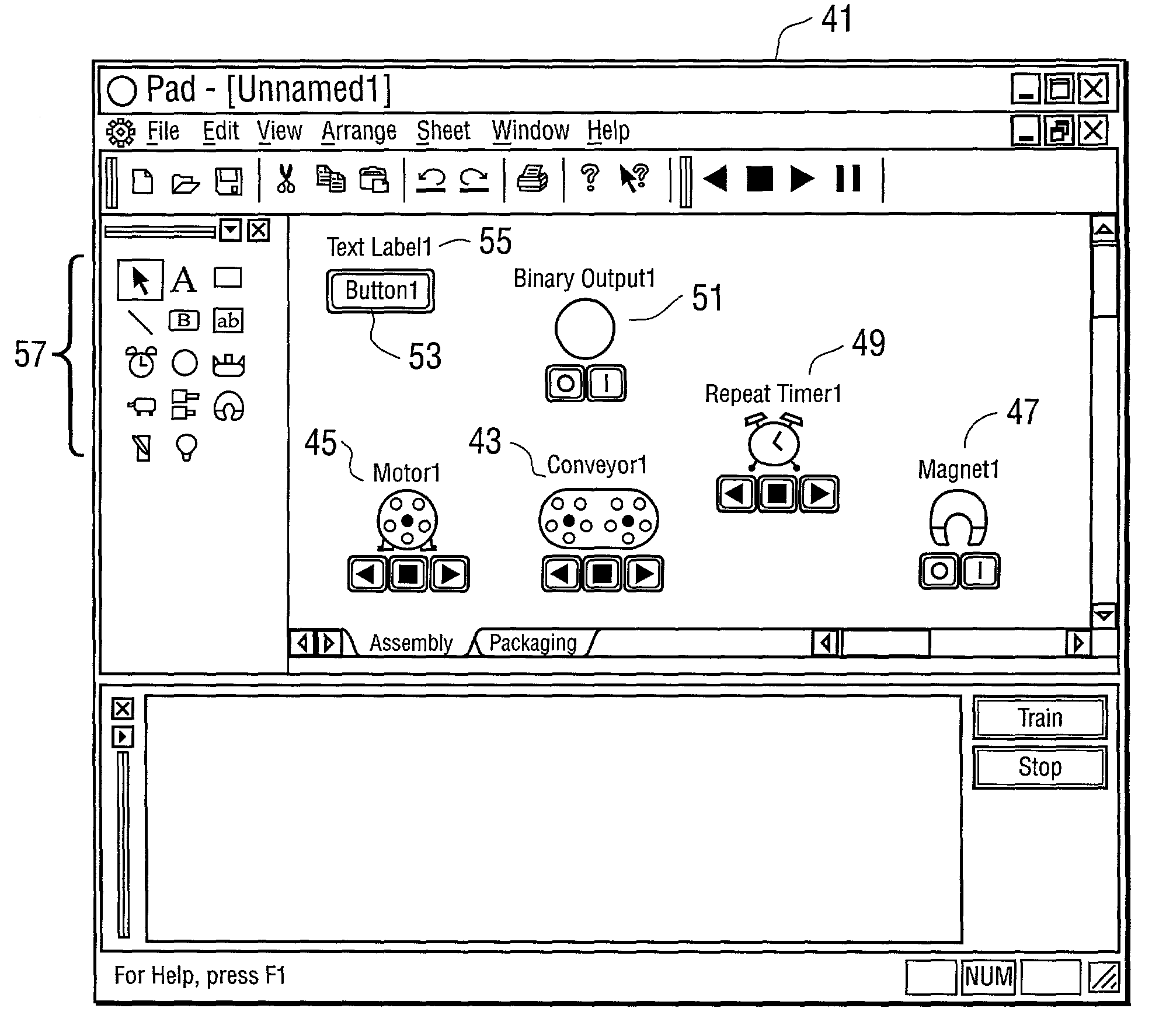
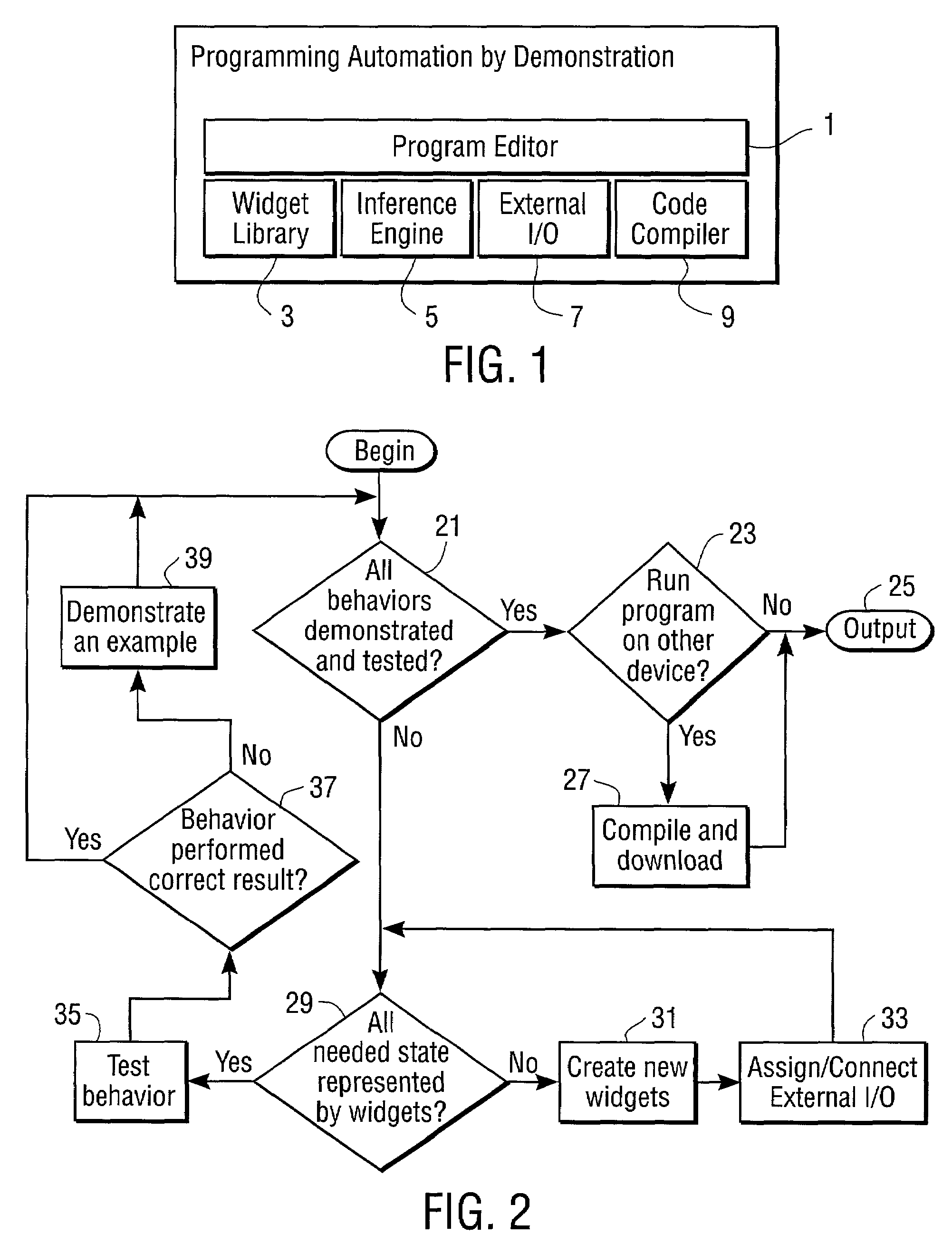
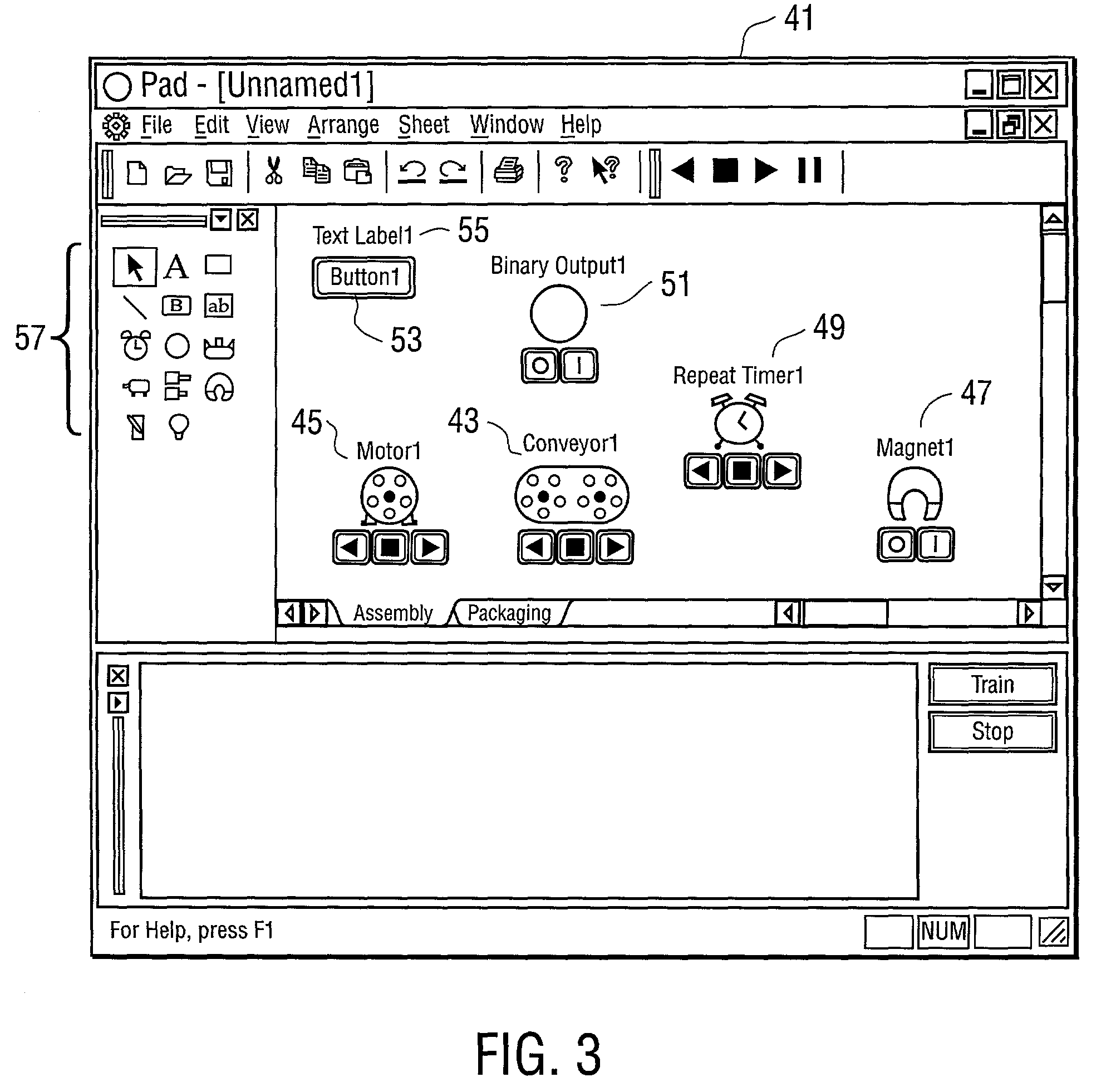
[0026]The present invention uses a technique called “programming by demonstration” to greatly simplify the task of programming in automation applications, where real physical objects, such as sensors and other equipment, are manipulated. Unlike the conventional control programming languages and tools typically used in automation environments, the programmer demonstrates the desired behavior of the control program by manipulating graphical representations of physical machines, devices, and programming elements. In a preferred embodiment, the actions performed by the user are combined by means of an inferencing engine to produce executable programs that run in the editor environment on a primary machine (e.g., Windows-based PC) or may be compiled and run on a different platform secondary machine such as a PLC. In other specific embodiments, the primary (or secondary) platforms can be UNIX, Macintosh, or other machines (e.g., palm computing device, wristwatch, etc.). The process of usi...


PUM


Abstract

A system for programming automation by demonstration where a control program may be created or modified through the process of demonstrating desired behavior using graphical representations (or widgets) of physical, programming, and user interface elements. Widgets have state, or properties, and may also have inherent events associated with them or indirect events that are generated through the demonstration process. The general process of demonstration consists of providing several individual example behaviors. Complete behavior, and thus the resultant code, is generated through inferencing from a number of individual example behaviors. The process of programming automation by demonstration reduces the complexity of the programming task and thereby greatly simplifies the workload of the control programmer, allowing the programmer to concentrate more on the specific automation application at hand rather than on the particulars of the programming language or tools. The invention may be applied to a wide range of automation applications, from home and building automation to industrial automation, and may be practiced by novice and expert-level users.

Description

CROSS-REFERENCE TO RELATED APPLICATION[0001]The present application claims priority from provisional U.S. patent application Ser. No. 60 / 186,969 filed Mar. 6, 2000 entitled “Programming Automation By Demonstration” and listing inventors Richard Gary McDaniel, Daniel Conrad Benson, Steven Michael Schofield and Frank Dittrich Schiller.BACKGROUND OF THE INVENTION[0002]The present invention relates to computer-controlled automation of physical objects / equipment and in particular to the process of creating and modifying control programs for operating and monitoring automation processes and equipment in the industrial or other automation environments.[0003]Modem industrial or other automation processes require the coordinated execution of several interdependent tasks by many different machines and pieces of equipment. The complexity of automation applications, the large number of signals and their interactions, as well as the increasing need for flexibility has resulted in the widespread ...

Claims


Application Information

Patent Timeline
IPC IPC(8): G05B11/01G05B15/00G05B19/42G06F9/44G05B19/042
CPCG05B19/0426G05B2219/23246G05B2219/23258G05B2219/23283
Inventor MCDANIEL, RICHARD GARYBENSON, DANIEL CONRADSCHOFIELD, STEVEN MICHAELSCHILLER, FRANK DITTRICH
Owner SIEMENS CORP
Learn More