
Analog interface for digital instrumentation

Inactive Publication Date: 2009-03-03
BEYERLE ALBERT G
View PDF11 Cites 8 Cited by
  • Summary
  • Abstract
  • Description
  • Claims
  • Application Information

AI Technical Summary

Problems solved by technology

Although this migration has enabled a wider scope of capability, it lacks the universality of the older analog methods and makes it difficult, if not altogether impossible, for different components of a spectroscopy system to interface.
Unlike their older analog counterparts, digital processing components made by a first manufacturer are usually unable to interface with digital processing components made by a different manufacturer.
This confines the user to a system having components from only one manufacturer, thereby restricting the generality of use for each component and preventing a full optimization of the system.
Moreover, older analog legacy components integral to many systems are rendered obsolete when any part of the system is replaced with a digital interface, requiring most or all of the system to be replaced.
Consequently, such incompatibility is indeed a serious limitation, often presenting financial barriers that are simply insurmountable.
The second communication protocol is incompatible with the first communication protocol.

Method used


Image

  • Analog interface for digital instrumentation
  • Analog interface for digital instrumentation
  • Analog interface for digital instrumentation

Examples


Embodiment Construction

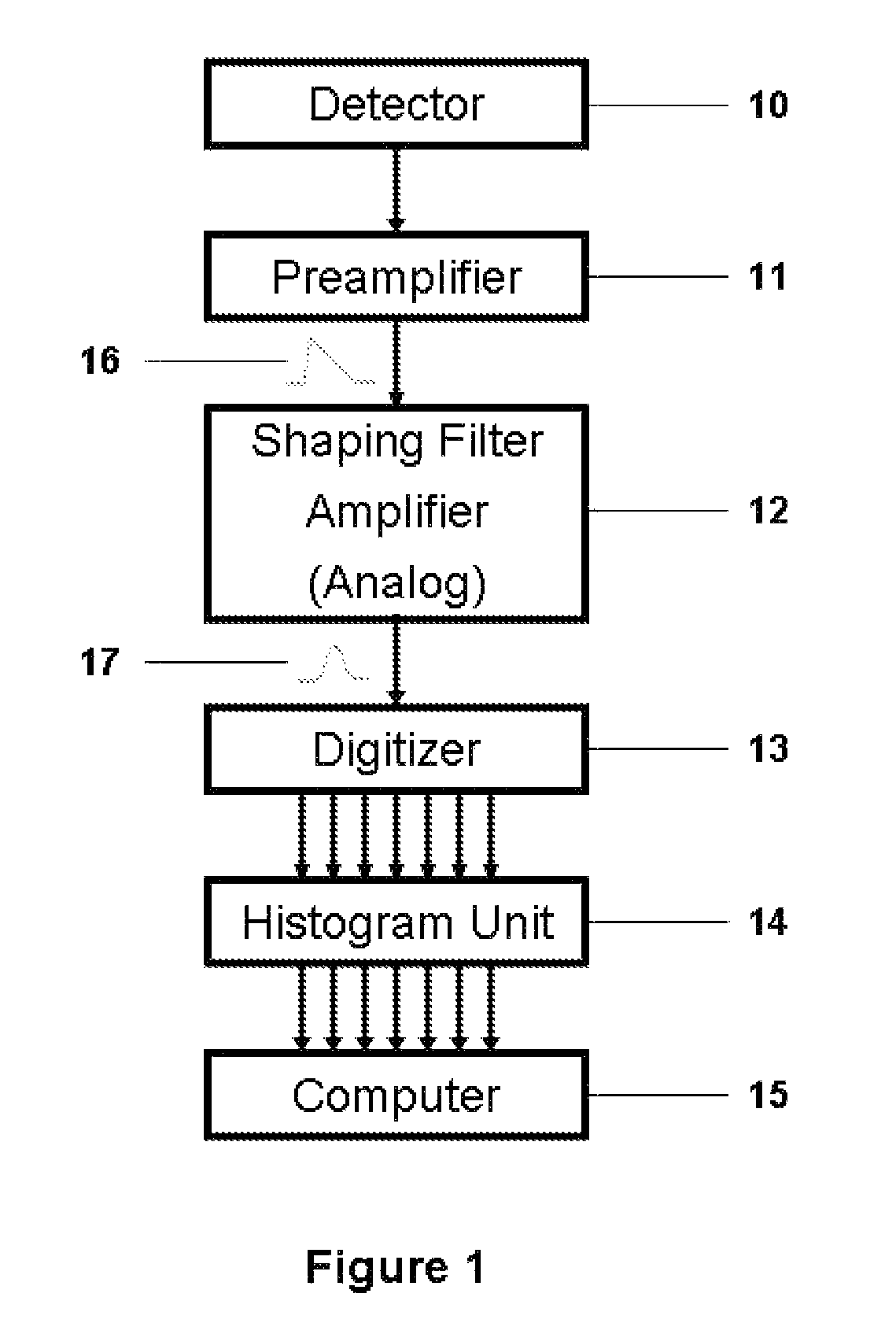
[0007]The term “analog data”, as used herein, is descriptive of a continuous pulse, wherein the pulse level at any given point represents the voltage level of an electrical signal. Analog data is indicated in the drawings by a single arrow.

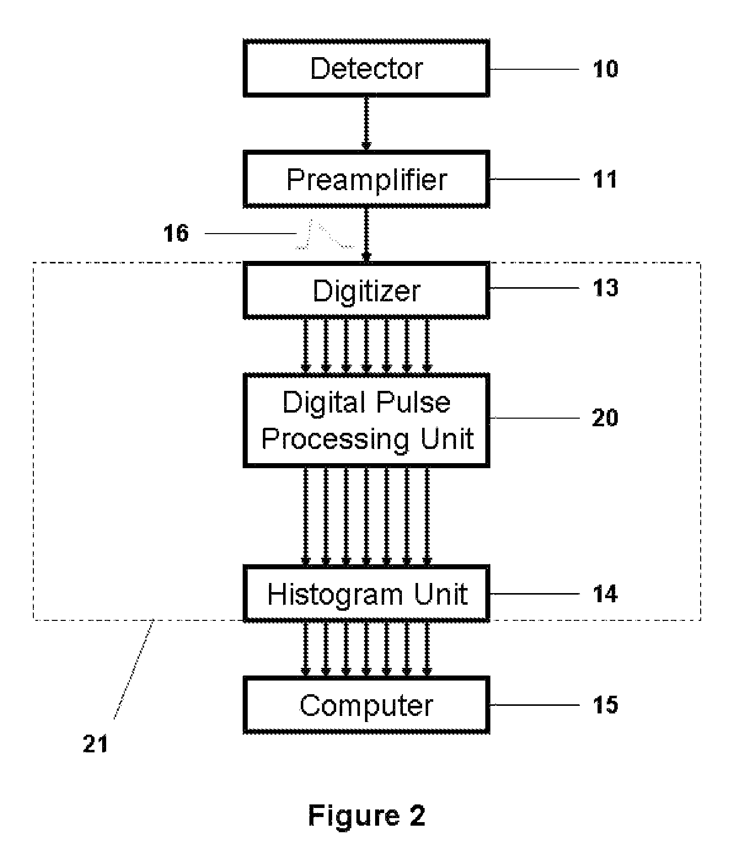
[0008]The term “digital data”, as used herein, is descriptive of a list of numbers representing the voltage level of an electrical signal at regularly spaced time intervals. Unlike analog data, digital data is not continuous. Digital data is indicated in the drawings by a group of seven parallel arrows.

BRIEF DESCRIPTION OF THE FIGURES

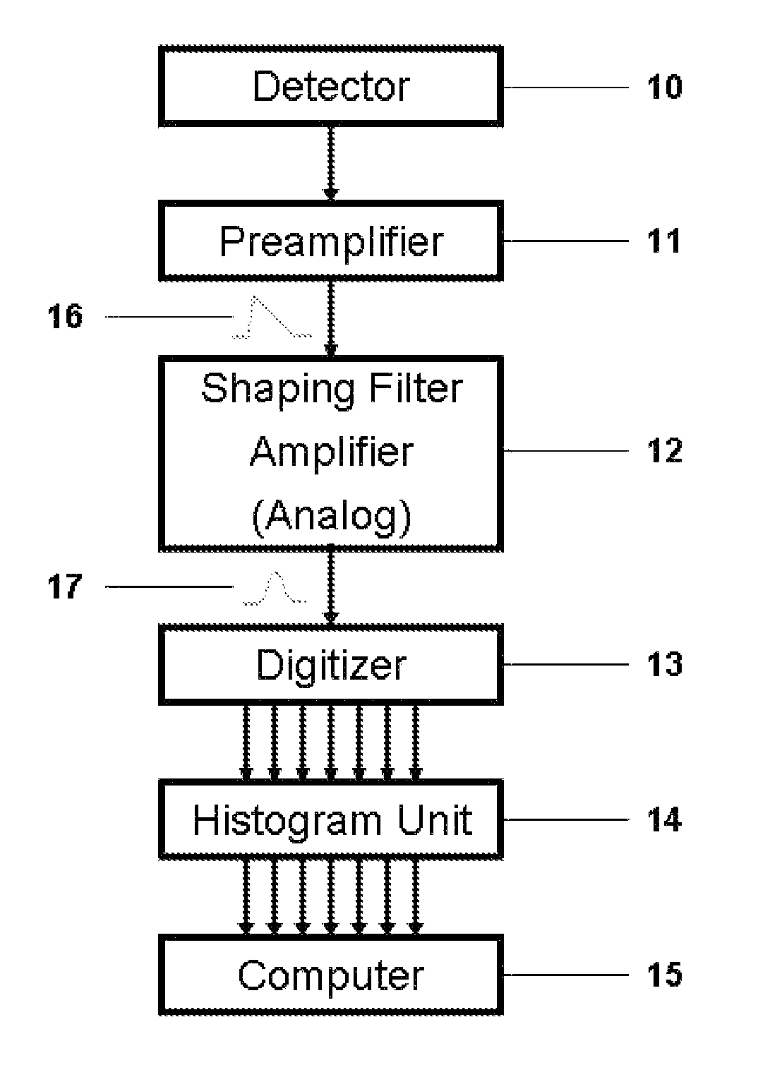
[0009]FIG. 1 shows a conceptual schematic of a traditional analog system.

[0010]FIG. 2 illustrates a more modern digital system.

[0011]FIG. 3 indicates the process of simulating an analog signal.

[0012]FIG. 4 shows a nuclear spectroscopy system using the simulation procedure of the present invention.

DESCRIPTION OF NUMERALS USED IN THE FIGS.

[0013]10—detector and its processing electronics[0014]11—preamplifier[0015]12—shap...


PUM


Abstract

Nuclear spectroscopy systems have improved over the course of time especially with the advent of digital pulse processing. One disadvantage of digital processing, however, is that it has eliminated the older, universally compatible interface standard of analog signals. Digital component interfaces are often defined by computer software, protected by copyright and unique to a single manufacturer. Consequently, all components of an entire spectroscopy system must be from a single manufacturer. This not only dictates system wide component replacement, but also impedes optimization that would otherwise occur were component compatibility the rule rather than the exception. The present innovation describes a method and apparatus to relieve the present incompatibility between digital components of a nuclear spectroscopy system that are supplied by more than one manufacturer.

Description

[0001]The present invention relates to signal processing instrumentation and techniques as applied to nuclear spectroscopy systems.BACKGROUND AND PRIOR ART[0002]Nuclear spectroscopy systems have enjoyed significant improvements over the past few years due, in part, to a widespread trend away from older analog signal processing in favor of the newer digital pulse processing methods. Although this migration has enabled a wider scope of capability, it lacks the universality of the older analog methods and makes it difficult, if not altogether impossible, for different components of a spectroscopy system to interface. Unlike their older analog counterparts, digital processing components made by a first manufacturer are usually unable to interface with digital processing components made by a different manufacturer. This confines the user to a system having components from only one manufacturer, thereby restricting the generality of use for each component and preventing a full optimizatio...

Claims


Application Information

Patent Timeline
IPC IPC(8): H03M1/00
CPCG01T1/17
Inventor BEYERLE, ALBERT G
Owner BEYERLE ALBERT G
Learn More