
Numerical display module for trail vehicles

a technology for trail vehicles and display modules, applied in anti-theft devices, cycle equipments, instruments, etc., can solve problems such as loss of control, increased danger of collisions between oncoming snowmobiles passing in opposite directions, and limitations of signaling methods, so as to increase the attention of signaling devices and ease the visibility of numerals

Inactive Publication Date: 2009-03-03
PEDRICK WILLIAM
View PDF11 Cites 8 Cited by
  • Summary
  • Abstract
  • Description
  • Claims
  • Application Information

AI Technical Summary

Benefits of technology

[0012]Further refinements are incorporated into the functionality of a preferred embodiment of the present invention. A “blink mode” is activated by the user to make the displayed numeral blink on and off consecutively and repeatedly, thereby allowing the user to attract even more attention to the signaling device. In addition, a “dim mode” is activated by the user during night travel to make the brightness of the numeral illuminated to become dimmer, thereby easing the visibility of the numeral to oncoming traffic during night time use.

Problems solved by technology

The increase in traffic has caused an increased danger of collisions between oncoming snowmobiles passing in opposite directions, especially on narrow trails with winding turns that create a limited line of sight.
Even in those trail areas where hand gestures are well understood, riders often forget to perform the hand signal, or the riders are wearing mittens that do not permit individual finger signals, or the riders are unable to remove one hand from their handle bars or steering system because they might lose a level of control over their trail vehicle.
This signaling method has limitations.
Second, the colored lights used by Brady et al. do not present any information about how many trailing vehicles are within that operator's party the oncoming operator should expect to meet.

Method used


Image

  • Numerical display module for trail vehicles
  • Numerical display module for trail vehicles
  • Numerical display module for trail vehicles

Examples


Embodiment Construction

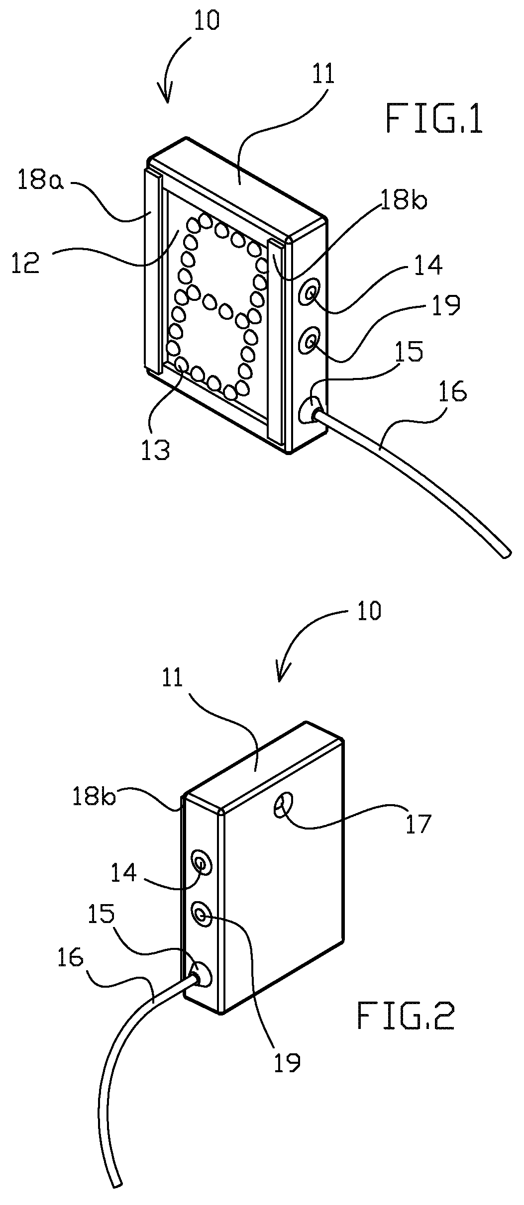
[0019]A preferred embodiment of a signaling device of the present invention is illustrated in FIGS. 1-2. FIG. 3 illustrates a snowmobile having a preferred embodiment of a signaling device of the present invention.

[0020]As previously noted, the signaling apparatus 10 can be used on different types of trail vehicles such as automobiles, all-terrain vehicles, and motorcycles. The signaling apparatus 10 is particularly desirable when used on snowmobiles 20 because they are often used to travel at high speeds on narrow trails with sharp bends and limited line of sight. The signaling apparatus 10 is useful in these conditions because operators of vehicles that are traveling in opposite directions on a common trail are informed of the number of vehicles that are traveling in each of the operators' respective parties. Each operator can steer their vehicle to the side of the trail until they know they have passed the last vehicle in the oncoming party of trail users.

[0021]In a preferred emb...


PUM


Abstract

An apparatus and method are presented which are used by operators of trail vehicles to share information with each other about the number of vehicles in their group of trail users. A display module attached to a vehicle displays a number which indicates how many vehicles are in that vehicle's party. As oncoming trail users pass each other, they can read the value of the displayed numeral and know instantly how many vehicles to expect before the path is clear of traffic. The display module projects a number which is changeable, user determined, and has optical properties that allow the drivers of passing vehicles to readily convey information to each other.

Description

BACKGROUND OF THE INVENTION[0001]1. Field of the Invention[0002]The present invention relates most generally to visual display devices used to communicate information between vehicles. More particularly, the present invention relates to devices which may be used to signal between oncoming operators of vehicles that are traveling in opposite directions on a common trail in order to convey the number of vehicles that are traveling in each of the operators' respective parties.[0003]2. Description of Related Art[0004]The figures illustrate the apparatus and method of the present invention used in conjunction with snowmobiles. However, the present invention can be used with all types of trail vehicles. Therefore, for the purposes of this specification and the claims, the term “trail vehicle” incorporates all transportation means on a recreational trail, including but not limited to snowmobiles, all-terrain multi-wheeled vehicles, cyclists, skaters, and skiers. Additionally, reasonable an...

Claims


Application Information

Patent Timeline
Patent Type & Authority Patents(United States)
IPC IPC(8): B62J3/00
CPCB60Q1/503G08G1/0962B60Q1/50B60Q1/5037B60Q1/545B60Q1/508
Inventor PEDRICK, WILLIAM
Owner PEDRICK WILLIAM
Learn More