
Fitting for tube and pipe with cartridge

a technology for fittings and pipes, applied in the direction of pipe joints, fluid pressure sealed joints, sleeves/socket joints, etc., can solve the problems of increasing manufacturing costs, requiring substantially larger blocks of material, and forged components that are typically unsuitable for high pressure applications, so as to reduce the overall length

Active Publication Date: 2009-03-03
SWAGELOK CO
View PDF39 Cites 51 Cited by
  • Summary
  • Abstract
  • Description
  • Claims
  • Application Information

AI Technical Summary

Benefits of technology

[0012]In accordance with another aspect of the invention, a ferrule type flareless fitting is provided that allows for easy installation by providing a single assembly that has one or more ferrules held with a fitting component. In one embodiment, a cartridge nut assembly allows one or more ferrules to be retained securely on a fitting component prior to installation so that the ferrules and the fitting component will not become separated prior to installation. In another embodiment of the invention, a tool is provided which retains the one or more ferrules onto a fitting component prior to installation and is removably during assembly.
[0014]In accordance with another aspect of the invention, a ferrule type flareless fitting is provided that includes a male nut that is flush with the body or recessed in the body when the fitting is in a pulled-up condition. In one embodiment, a keyed male nut, and corresponding key tool, is provided that has a hex area removed to reduce its overall length.

Problems solved by technology

More complex configurations, such as elbows and tee shapes, however, require substantially larger blocks of material.
For these types of fittings, a substantial amount of material must be removed, which can drive up manufacturing costs.
The forging process, however, can cause material annealing which eliminates any prior work hardening.
Thus, forged components are typically unsuitable for high pressure applications.

Method used


Image

  • Fitting for tube and pipe with cartridge
  • Fitting for tube and pipe with cartridge
  • Fitting for tube and pipe with cartridge

Examples


Embodiment Construction

[0047]This application fully incorporates by reference U.S. patent application Ser. No. 11 / 112,800 filed on Apr. 22, 2005 for FITTING FOR TUBE AND PIPE.

[0048]While the invention is described herein with specific reference to a variety of structural and material features, such descriptions are intended to be exemplary in nature and should not be construed in a limiting sense. For example, the exemplary embodiments are described primarily in terms of a stainless steel tube fitting for automotive applications. Those skilled in the art, however, will readily appreciate that any one or more of the aspects and features of the invention may be used outside of the automotive industry, can be used with materials other than stainless steel and can be used with many conduits including, but not limited to, tube or pipe. Moreover, many of the aspects of the invention may be used for lower pressure fittings, or the higher rated pressure concepts disclosed herein may be used in a fitting even when...


PUM


Abstract

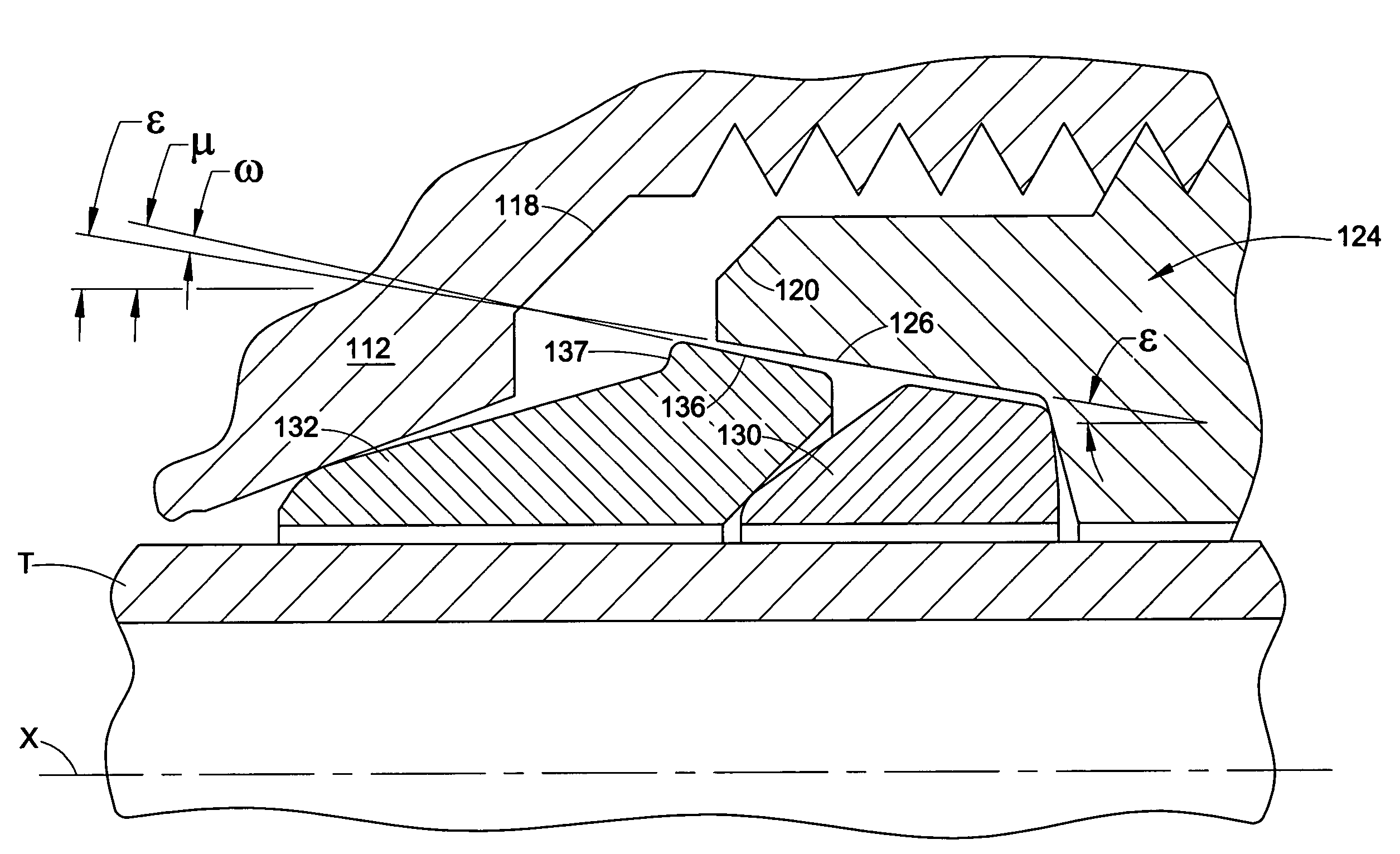
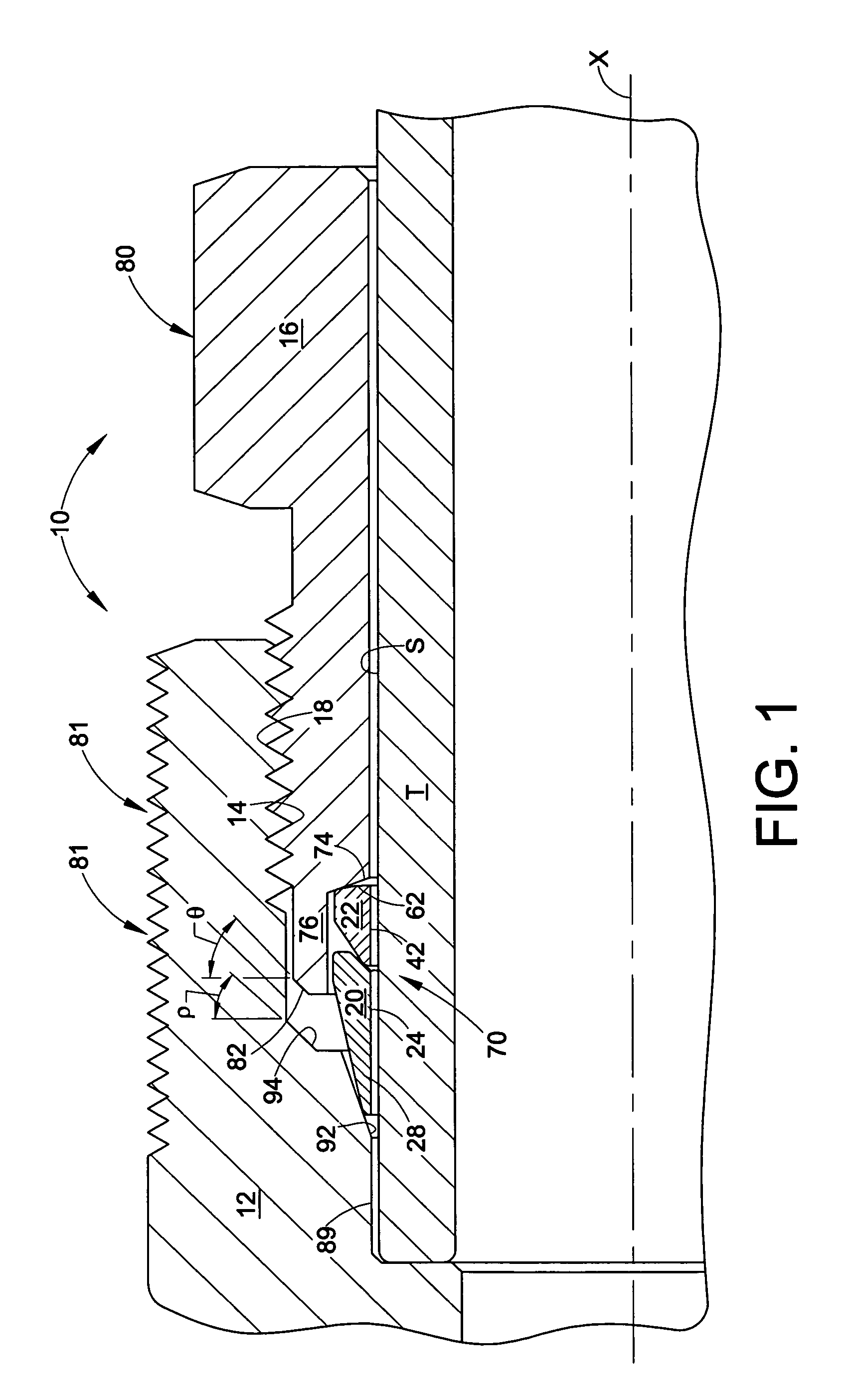
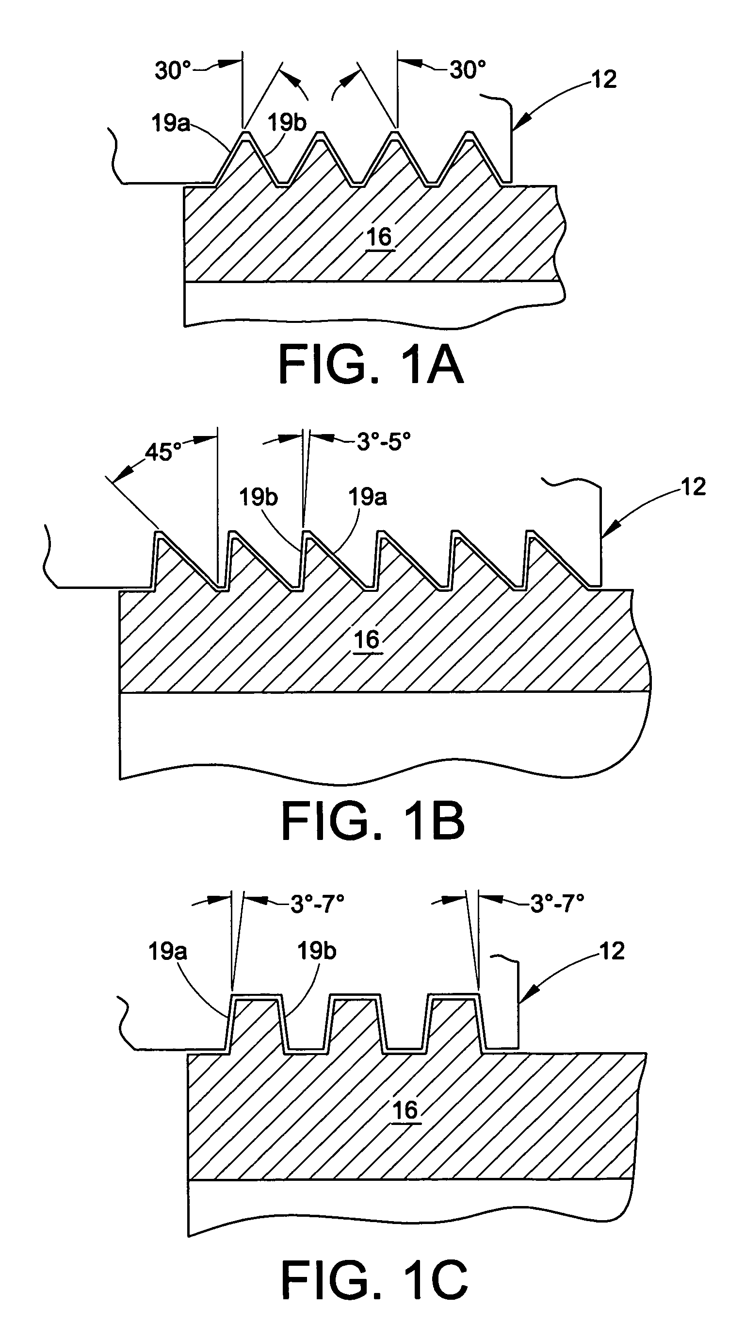
A fitting for a tube or pipe capable of functioning a high pressures having a first fitting component adapted to receive the conduit end; a conduit gripping device such as a ferrule or ferrules and a second fitting component that can be joined to the first fitting component to cause the conduit gripping device to grip the conduit and seal when assembled. In one aspect of the invention, the first fitting component is constructed from a material that is softer than the material used to construct the second fitting component. An additional aspect of the invention include a retaining portion on the second fitting component that constrains the tube gripping device against pressure. The retaining portion can also be configured to retain the tube gripping device to the second fitting component prior to installation and in a finger-tight condition. A further aspect of the invention includes a first fitting component in which an exterior portion of the component is work hardened radially outward from the tube gripping device. The fitting may optionally be provided with a structure to effect the pull-up by torque functionality.

Description

[0001]This application is a continuation in part of co-pending U.S. patent application Ser. No. 11 / 112,800 filed on Apr. 22, 2005 for FITTING FOR TUBE AND PIPE, which Claims the benefit of U.S. provisional patent application Ser. Nos. 60 / 564,358 for HARDENED TUBE FITTING filed Apr. 22, 2004 and 60 / 633,885 for FITTING FOR TUBE AND PIPE filed Dec. 7, 2004, the entire disclosures of which are fully incorporated Herein by reference.BACKGROUND OF THE INVENTION[0002]Flareless fittings have been in use for decades for conduits such as tubes and pipes. A flareless fitting is used to connect or join two tube or pipe ends or to connect a conduit end to another assembly such as a tank, a valve, a manifold and so on. The applications are as varied as the types of assemblies with which the fittings are used. One very common type of flareless fitting is a ferrule type fitting. In a ferrule type fitting, one or more ferrules are used to join or connect a conduit end to a fitting member, typically ...

Claims


Application Information

Patent Timeline
Patent Type & Authority Patents(United States)
IPC IPC(8): F16L13/14F16L19/06F16L25/00
CPCF16L19/06F16L19/061F16L19/103
Inventor WILLIAMS, PETER C.CLASON, MARKMARSHALL, ANDREWFRUH, JASONKVARDA, ERIC M.
Owner SWAGELOK CO
Learn More