Technique for predicting over insertions for partial grids and defective Z-pins

a partial grid and z-pin technology, applied in the field of reinforced composites, can solve the problems of excessive force being applied to the pins, failure mode typically occurring at the inner hat stiffener to the skin surface, and failure to automate the z-pin process

Inactive Publication Date: 2009-03-03
NORTHROP GRUMMAN SYST CORP
View PDF25 Cites 2 Cited by
  • Summary
  • Abstract
  • Description
  • Claims
  • Application Information

AI Technical Summary

Benefits of technology

[0012]In accordance with the present invention, there is provided a system for facilitating a two speed insertion process for Z-pinning / joining uncured composite laminates to each other. The insertion process of the present invention employs the use of an ultrasonic horn which is used to deliver ultrasonic energy to the Z-pins within a Z-pin carrier pre-form. In the insertion process, the insertion speed is changed to a lower insertion speed based on the force resistance encountered during insertion, providing a tactile feedback system. No operator intervention is needed as the system adapts to the prevailing conditions. By using this two speed process, it is possible to insert Z-pins into a wider variety of composite laminate conditions that would be impossible using single speed insertion techniques.

Problems solved by technology

However, in both this process and that wherein the hat stiffeners were mechanically bolted and / or adhesively bonded to the skin, the failure mode typically occurred at the inner hat stiffener to skin surface.
However, attempts at automating the Z-pinning process have proven challenging due to the need for special techniques to accommodate the many variables involved with the Z-pinning process.
Inserting the Z-pins too fast results in excessive force being applied to the pins, thereby crushing them, or causing them not to penetrate completely through the parts being joined.
Inserting the Z-pins too slowly takes excessive time thereby not achieving a reasonable return on investment, or causes the pre-form to overheat which creates a potential for a fire hazard.
When an ultrasonic horn is used, increasing the amplitude of the horn oscillation allows for faster insertion, but increases the risk for transferring too much energy into the pre-form causing over-insertion of the Z-pins and melting of the pre-form.
Moreover, one set of conditions may be fine for a new material and a thin total thickness, but not optimal for an aged material (e.g., a thirty day age material) that is of a maximum thickness.
Indeed, since many of the aforementioned variables interact in a non-linear fashion, it is extremely difficult to predict insertion success with any given combination.
However, with currently known manual insertion processes, follow-up manual inspection steps are still typically required to verify that the Z-pins were inserted to the full, proper depth.
Inferior Z-pins are unable to carry the normal insertion forces exerted by the robotic system and thus often crumble instead of fully inserting into the underlying composite structure.
The effect of inserting this partial grid is to cause over insertions, which typically causes one or more of the following conditions: (1) the Z-pins on top of the carrier pre-form are crushed, thus causing a blackening of the surface of the underlying substrate and creating a cosmetic problem; (2) the time to complete the insertion is increased, often to a maximum value of six seconds, thus wasting extra time for no purpose; (3) the carrier pre-form is heated up beyond normal, causing the low density foam (polystyrene) included therein to melt; and (4) the maximum insertion depth for the Z-pins is often reached, again wasting valuable time.
Occasionally, the quality of the Z-pins themselves is questionable as they sometimes are unable to carry the insertion force even on a full grid insertion, thus causing the Z-pins to crumble and not fully insert.
This tends to be a more serious problem than over insertion as it could result in the parts not being pinned with enough integrity to maintain structural strength in the joint.

Method used


Image

  • Technique for predicting over insertions for partial grids and defective Z-pins
  • Technique for predicting over insertions for partial grids and defective Z-pins
  • Technique for predicting over insertions for partial grids and defective Z-pins

Examples


Embodiment Construction

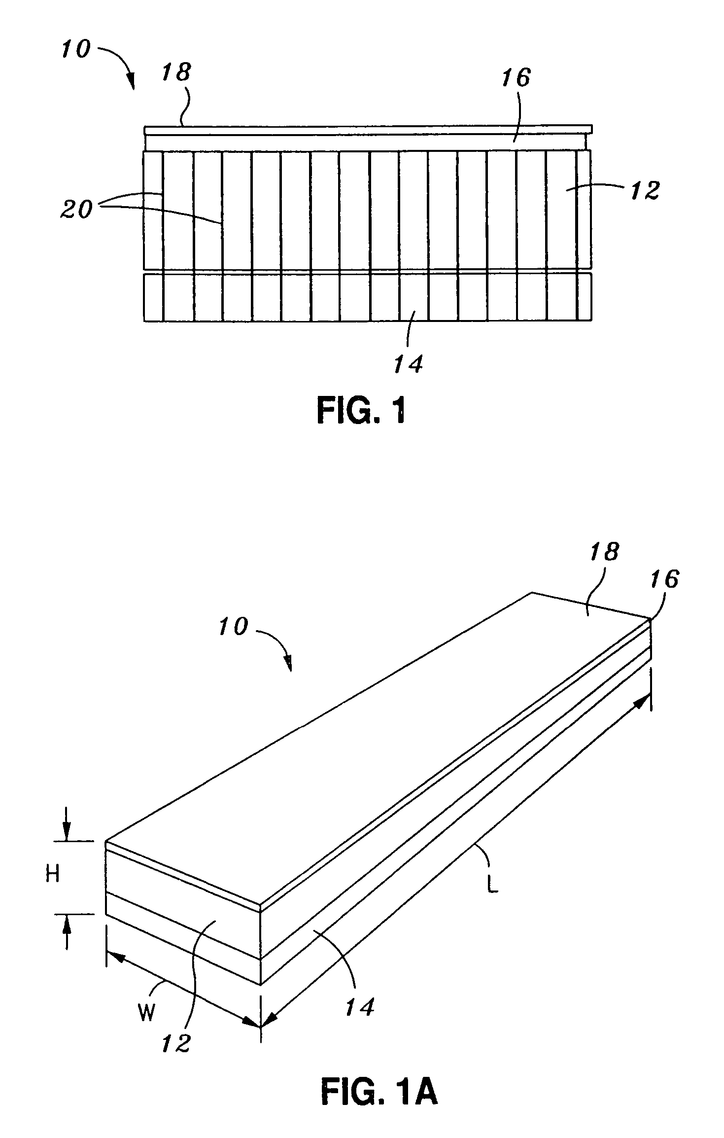
[0032]Referring now to the drawings wherein the showings are for purposes of illustrating preferred embodiments of the present invention only, and not for purposes of limiting the same, FIGS. 1 and 1A provide cross-sectional and top perspective views, respectively, of an exemplary Z-pin carrier pre-form 10 which may be used in the Z-pinning process of the present invention as will be described in more detail below. The carrier pre-form 10 comprises an upper layer 12 of low density foam and a lower layer 14 of high density foam which is contiguous with the upper layer 12. In this regard, the top surface of the lower layer 14 is abutted against the bottom surface of the upper layer 12. Covering the top surface of the upper layer 12 is a layer 16 of polyolefin. The layer 16 is in turn covered by a layer 18 which is fabricated from paper. As such, the layer 16 is disposed between the layer 18 and the upper layer 12.

[0033]In addition to the layers 12, 14, 16, 18, the carrier pre-form 10 ...


PUM

PropertyMeasurementUnit
timeaaaaaaaaaa
insertion speedaaaaaaaaaa

Abstract

In accordance with the present invention, there is provided a technique which may be used in conjunction with an automated Z-pin insertion process to automatically monitor the insertion energy applied to the Z-pins during the initial insertion phase of the automated insertion process, and compare it to an empirically derived value for good insertions, thereafter allowing the insertion process to continue to a predetermined additional insertion depth before terminating the process. The insertion energy is calculated by cumulatively summing the insertion force and multiplying it by the insertion time, thus yielding the cumulative energy. At a specified, predetermined insertion depth, the energy accumulation is stopped and the value at the initial insertion depth is stored and compared to an empirically derived value. If the value is less than the empirical value, the insertion energy is too low, thus indicating that either a partial grid insertion is being encountered or defective Z-pins are being inserted. Insertion is allowed to continue until another empirically derived second insertion depth is reached whereat the insertion is terminated. The second depth is necessary for the continued insertion of partial grids to ensure that the Z-pins are fully inserted. The second depth is a function of the laminate thickness to ensure full depth insertions.

Description

CROSS-REFERENCE TO RELATED APPLICATIONS[0001]The present application is a continuation-in-part of U.S. application Ser. No. 11 / 158,400 entitled now U.S. Pat. No. 7,409,757 B2 AUTOMATED Z-PIN INSERTION TECHNIQUE USING UNIVERSAL INSERTION PARAMETERS filed Jun. 22, 2005, the disclosures of which are incorporated herein by reference.STATEMENT RE: FEDERALLY SPONSORED RESEARCH / DEVELOPMENT[0002]The invention disclosed in the present application was developed under a contract research and development (CRAD) program funded by the Office of Naval Research (ONR).BACKGROUND OF THE INVENTION[0003]The present invention relates generally to reinforced composites, and more particularly, to a two-speed insertion process for Z-pinning / joining uncured composite laminates to each other.[0004]The use of composites as primary structures in aerospace applications is becoming increasingly widespread in the aerospace industry. Traditional composite materials are made up of a resin matrix material and a quan...

Claims


Application Information

Patent Timeline
Patent Type & Authority Patents(United States)
IPC IPC(8): B23P11/00B23Q17/00
CPCB29C65/08B29C66/112B29C66/131B29C66/474B29C66/721B29C66/8322B29C66/92443B29C66/939B29C70/24B29C66/524B29C66/961B29C66/9221B29C66/93441B29C66/9392B29C65/564Y10T29/49776B29C66/91231B29C66/929B29C66/949B29K2101/10B29K2101/12B29K2277/10B29K2307/00B29K2309/08B29L2031/3076Y02T50/433Y10T29/5343Y10T29/49764Y10T29/49771Y10T29/4978Y10T29/49833Y10T29/49959B29C66/8246B29C66/73752B29C66/73921B29C66/73941B29C66/7212B29C66/9292B29C66/863Y02T50/40B29K2307/04
Inventor HALL, TERENCE F. W.BARTLEY-CHO, JONATHAN D.
Owner NORTHROP GRUMMAN SYST CORP
Why Eureka
Try Eureka