
System and method for monitoring reliability of a digital system

a digital system and reliability technology, applied in the field of failure prediction, can solve problems such as degradation of digital system performance or reliability, undetected errors in computation, and inability to provide aging information for each specific digital system of the type being manufactured

Inactive Publication Date: 2009-02-24
KYNDRYL INC
View PDF30 Cites 52 Cited by
  • Summary
  • Abstract
  • Description
  • Claims
  • Application Information

AI Technical Summary

Benefits of technology

The patent describes a system and method for monitoring the reliability of a digital system by using a ring oscillator sensor embedded in the system. The sensor's output is converted to an oscillation frequency, which is periodically evaluated and compared to a threshold to generate a warning signal if there is a degradation in the sensor's performance. This system can help alert the user when the digital system is no longer operating reliably, and can also help improve the overall reliability of the system by identifying and addressing any issues with the sensor.

Problems solved by technology

Although burn-in testing of digital systems attempts to predict a lifecycle for a given type of digital system, it does not provide aging information for each specific digital system of the type being manufactured.
Currently, a customer or user may uncover a problem with a digital system only after a catastrophic system failure.
While catastrophic failure of a digital system is readily recognizable, a “soft” failure (where there may be significant degradation in digital system performance or reliability) may go unnoticed, which implies that such aging of the digital system may cause undetected errors in computation and data, from which it is difficult to recover.

Method used


Image

  • System and method for monitoring reliability of a digital system
  • System and method for monitoring reliability of a digital system
  • System and method for monitoring reliability of a digital system

Examples


Embodiment Construction

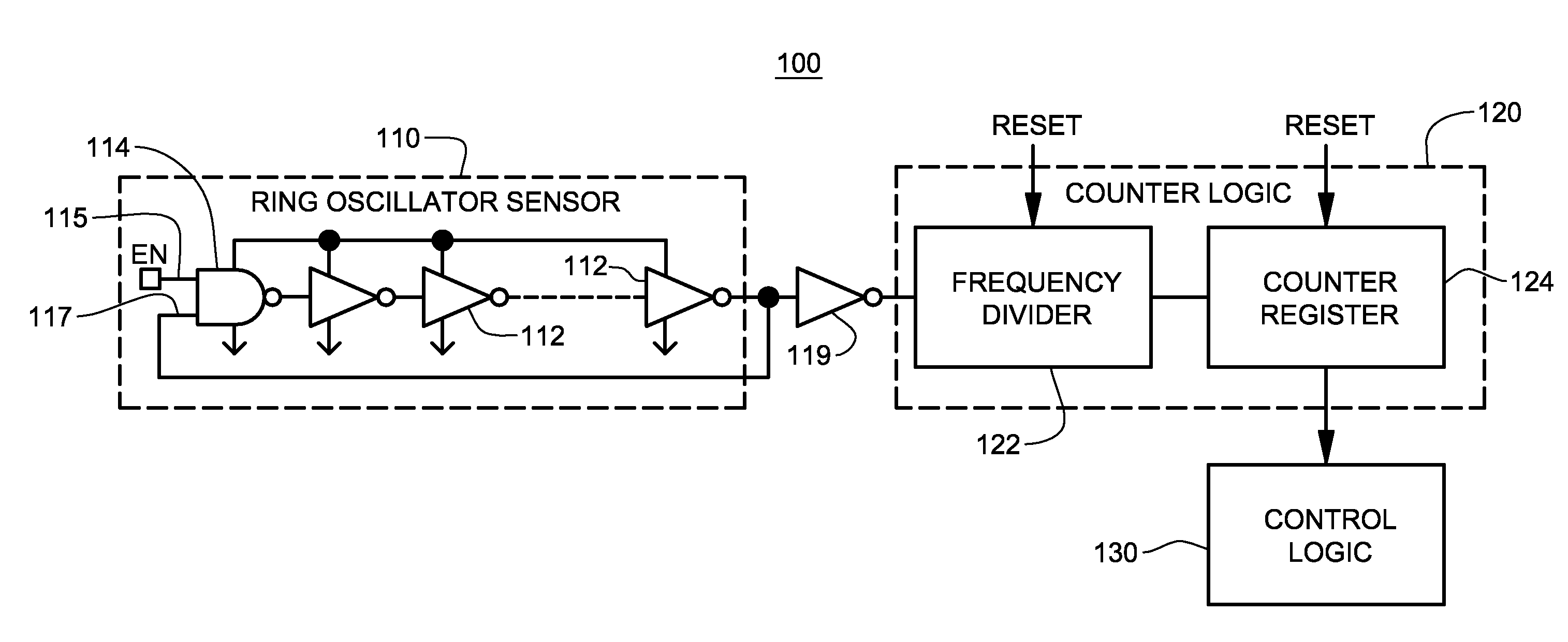
[0027]As noted, presented herein are a monitoring system and method for actively tracking aging, and hence reliability, of a specific digital system, and for issuing a warning signal if, for example, degradation of the monitoring system exceeds a pre-specified threshold. The “digital system” refers to any digital system or circuit, and includes, for example, a processor, as well as simple or complex non-processor based digital logic, memory, etc. As one specific example, the digital system is a microprocessor, and the specified threshold is a predefined acceptable level for the maximum frequency of operation of the digital system.

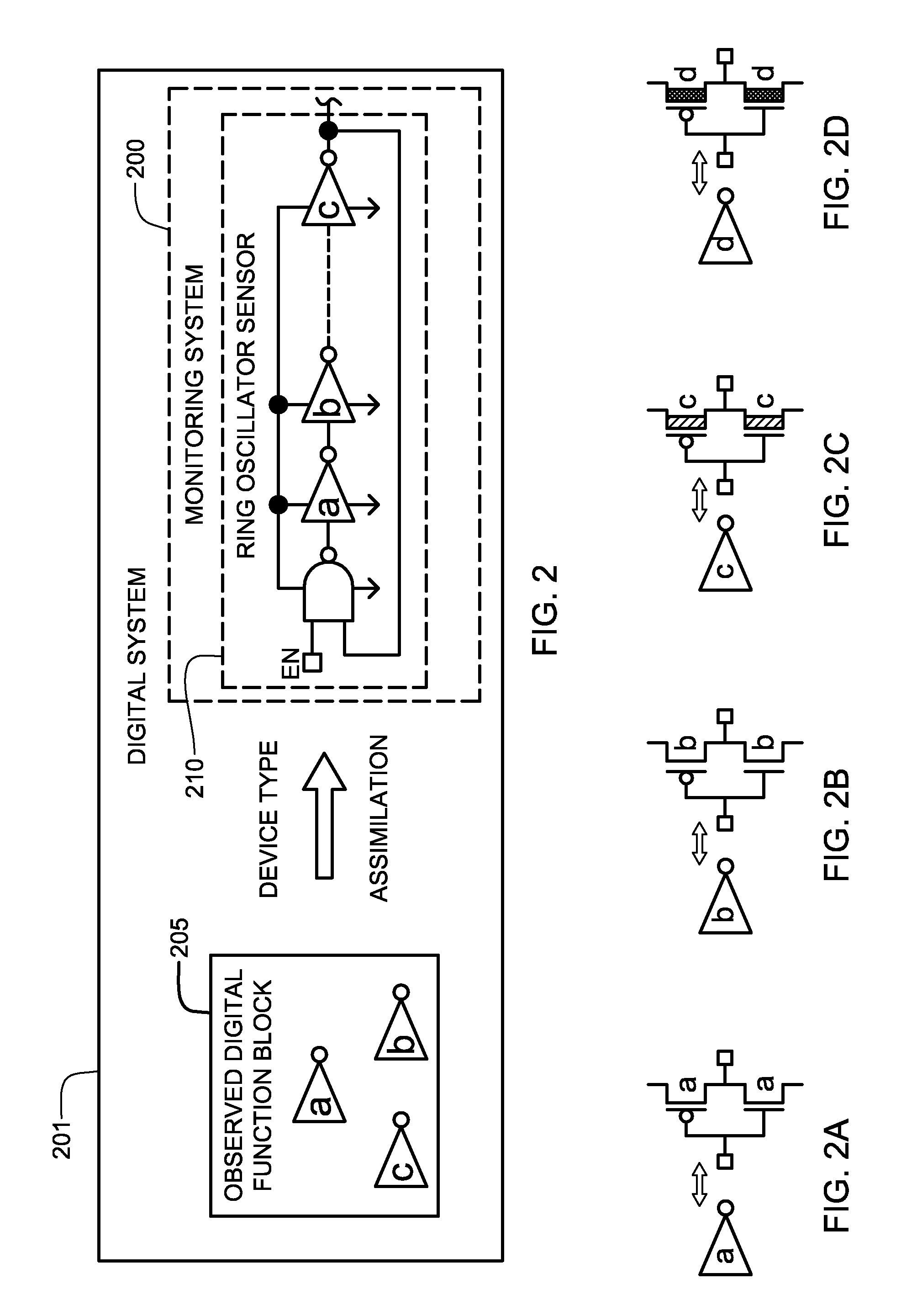
[0028]More particularly, presented herein is a technique for monitoring reliability of a digital system employing one or more ring oscillator sensors implemented in association with (e.g., embedded within) the digital system. In one embodiment, the one or more ring oscillator sensors are integrated into the digital system within available space thereof. As ...


PUM


Abstract

System and method are provided for continually monitoring reliability, or aging, of a digital system and for issuing a warning signal if digital system operation degrades past a specified threshold. The technique includes implementing a ring oscillator sensor in association with the digital system, wherein logic and / or device percent composition of the ring oscillator sensor mirrors percent composition thereof within the digital system. Counter logic is coupled to the ring oscillator sensor for converting outputted count signals to an oscillation frequency, and control logic is coupled to the counter logic for periodically evaluating oscillation frequency of the ring oscillator sensor and generating a warning signal indicative of reliability degradation if at least one of: (i) a measured or estimated oscillation frequency is below a warning threshold frequency; or (ii) a measured or estimated rate of change in a difference between measured oscillation frequencies exceeds an acceptable rate of change threshold.

Description

TECHNICAL FIELD[0001]The present invention relates in general to the field of failure prediction and, more specifically, to a ring oscillator sensor-based reliability measurement system and method for a digital system.BACKGROUND OF THE INVENTION[0002]Failure rates of individual components making up a digital system such as an integrated circuit (or larger system) are fundamentally related to various parameters, including operating temperatures, as well as scaling of the digital system and interconnect geometries. Although burn-in testing of digital systems attempts to predict a lifecycle for a given type of digital system, it does not provide aging information for each specific digital system of the type being manufactured. Currently, a customer or user may uncover a problem with a digital system only after a catastrophic system failure. While catastrophic failure of a digital system is readily recognizable, a “soft” failure (where there may be significant degradation in digital sys...

Claims


Application Information

Patent Timeline
Patent Type & Authority Patents(United States)
IPC IPC(8): G01R23/00H03B5/24H03K3/03
CPCG01R31/31725G01R31/31937G01R31/317G01R31/3193
Inventor KIM, DAE IKKIM, JONGHAEKIM, MOON JUMOULIC, JAMES R.SONG, HONG HUA
Owner KYNDRYL INC
Learn More