
Apparatus and method for PFM buck-or-boost converter with smooth transition between modes

a technology of buck-or-boost converter and smooth transition, applied in the field of converters, can solve the problems of large output ripple and glitches of conventional bob regulators, and inferior topologies to boost and buck regulation for efficiency,

Active Publication Date: 2009-02-24
NAT SEMICON CORP
View PDF8 Cites 231 Cited by
  • Summary
  • Abstract
  • Description
  • Claims
  • Application Information

AI Technical Summary

Problems solved by technology

However, these topologies are inferior to both boost and buck regulation for efficiency and other reasons.
However, buck / boost mode is inferior to buck mode or boost mode in terms of efficiency and other performance parameters.
However, conventional BOB regulators typically have large output ripple and glitches when changing from buck mode to boost mode or vice versa.

Method used


Image

  • Apparatus and method for PFM buck-or-boost converter with smooth transition between modes
  • Apparatus and method for PFM buck-or-boost converter with smooth transition between modes
  • Apparatus and method for PFM buck-or-boost converter with smooth transition between modes

Examples


Embodiment Construction

[0015]Various embodiments of the present invention will be described in detail with reference to the drawings, where like reference numerals represent like parts and assemblies throughout the several views. Reference to various embodiments does not limit the scope of the invention, which is limited only by the scope of the claims attached hereto. Additionally, any examples set forth in this specification are not intended to be limiting and merely set forth some of the many possible embodiments for the claimed invention.

[0016]Throughout the specification and claims, the following terms take at least the meanings explicitly associated herein, unless the context dictates otherwise. The meanings identified below do not necessarily limit the terms, but merely provide illustrative examples for the terms. The meaning of “a,”“an,” and “the” includes plural reference, and the meaning of “in” includes “in” and “on.” The phrase “in one embodiment,” as used herein does not necessarily refer to ...


PUM


Abstract

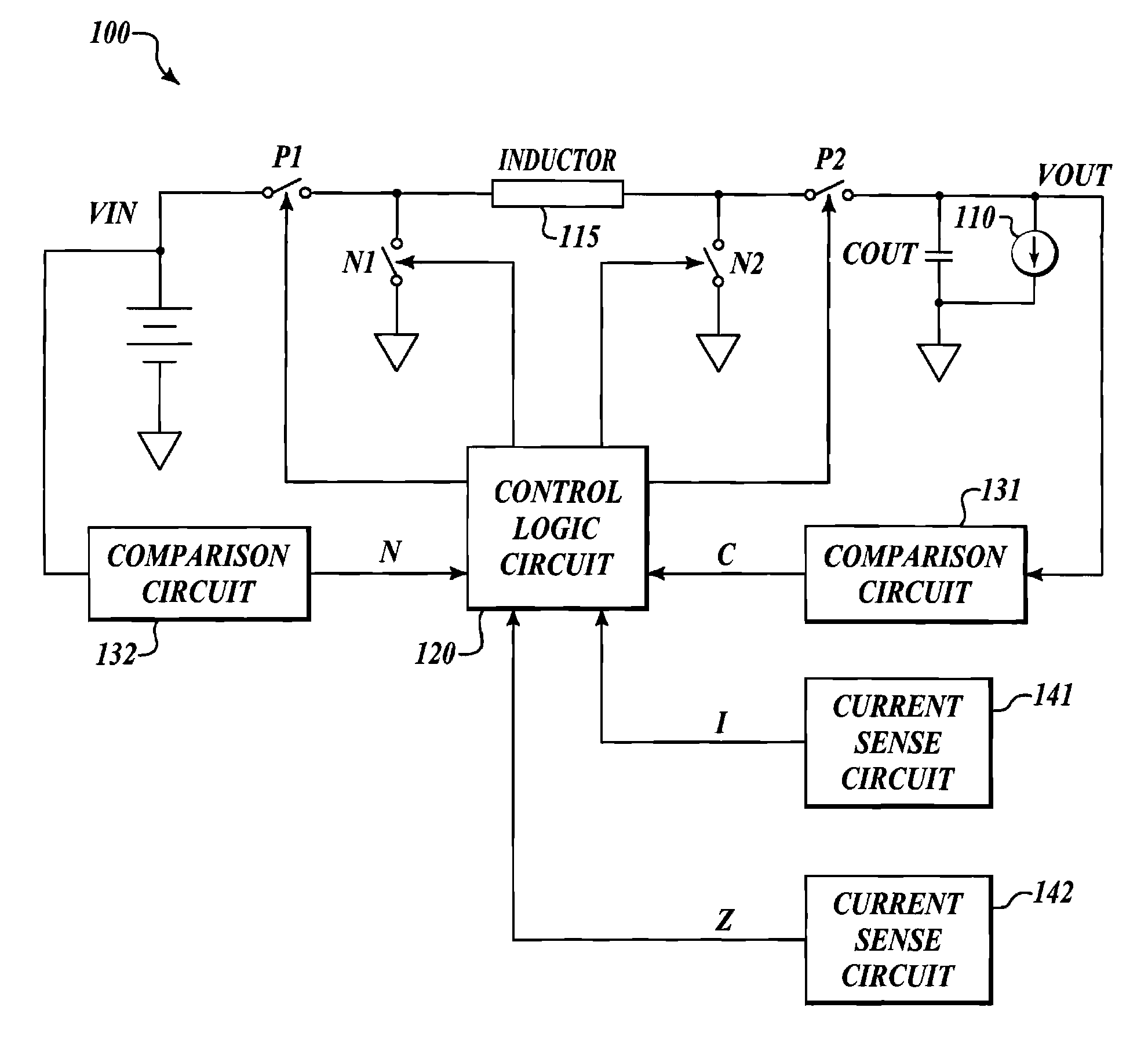
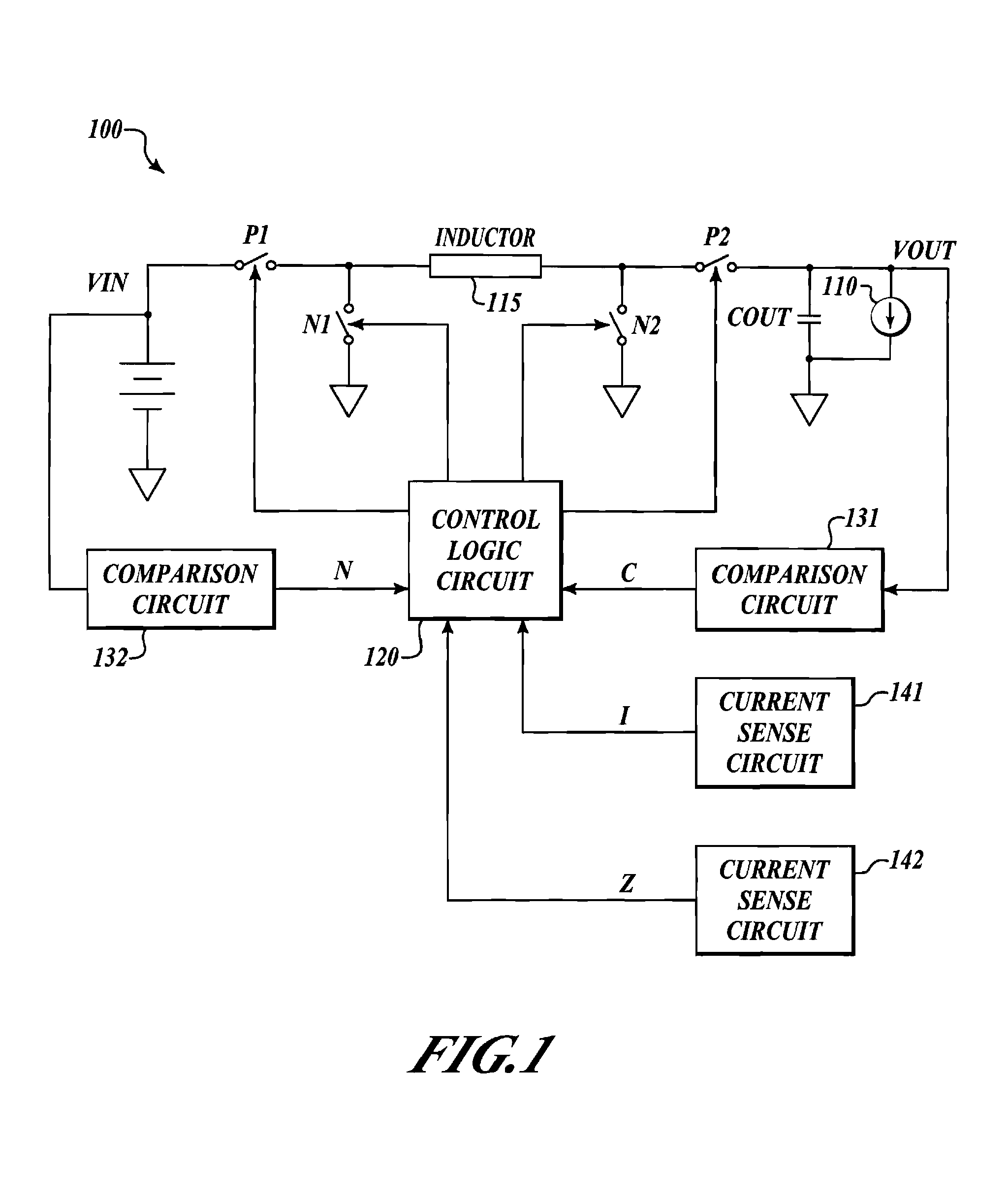
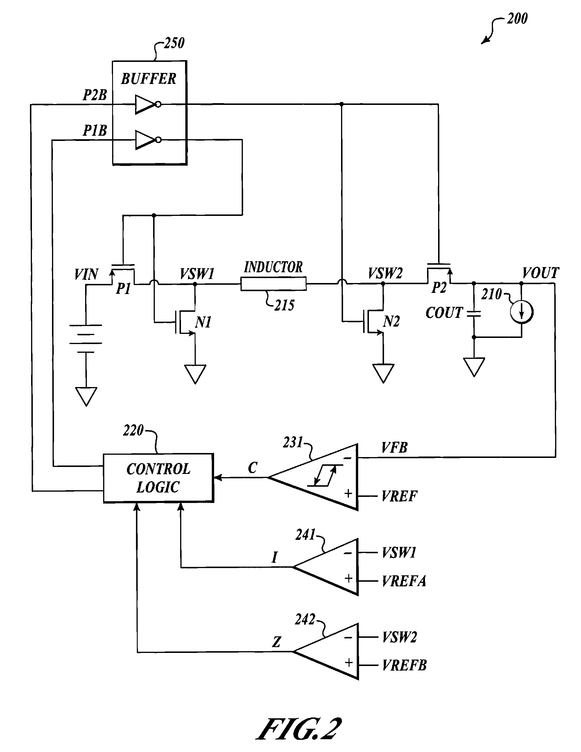
A PFM buck-or-boost converter is provided. The converter includes, inter alia, a hysteretic comparator, current sense circuitry, a logic circuit, drivers, current sense circuitry, a first buck switch, and a first boost switch. The current sense circuitry asserts signal Z if the current through the boost switch (from the load to the inductor) is greater than zero, and unasserts Z otherwise. Additionally, the current sense circuitry asserts signal I if the current through the buck switch is greater than a fixed current limit value, and unasserts I otherwise. The logic circuit employs the hysteretic comparator output, signal Z, and signal I to control the switches, and to determine whether to operate in buck regulation mode or boost regulation mode.

Description

FIELD OF THE INVENTION[0001]The invention is related to converters, and in particular, to an apparatus and method for a PFM buck-or-boost DC-DC converter with a smooth transition between buck and boost modes.BACKGROUND OF THE INVENTION[0002]A buck regulator may be used to generate a regulated output voltage than is less than the input voltage; conversely, a boost converter may be used to generate a regulated output voltage that is greater than the input voltage. However, DC-DC converters with step up / step down characteristics need to be used when the input and output voltage ranges overlap. Several different topologies may be used, such as SEPIC, Cuk, a one-mode buck / boost regulator, a three-mode buck / boost regulator, and the like. However, these topologies are inferior to both boost and buck regulation for efficiency and other reasons. A one mode buck / boost regulator operates in buck / boost mode only. A three-mode buck / boost regulator operates in three modes. If the input voltage is...

Claims


Application Information

Patent Timeline
Patent Type & Authority Patents(United States)
IPC IPC(8): G05F1/62
CPCG05F1/62H02M3/1582H02M3/1588Y02B70/1466Y02B70/10
Inventor JU, SHU-ING
Owner NAT SEMICON CORP
Learn More