
Network with redundancy properties, a branching unit for a user device in a network, redundancy manager for a network with redundancy properties and method for operating a network with redundancy properties

a network and redundancy property technology, applied in the field of network, can solve the problems of reducing system availability, affecting the communication of the other field devices connected to the bus cable, and failure to have particularly serious effects on system availability, so as to reduce the cycle time of test telegram injection, reduce the reaction time of the known method, and detect network errors comparatively quickly

Active Publication Date: 2009-02-17
SIEMENS AG
View PDF15 Cites 4 Cited by
  • Summary
  • Abstract
  • Description
  • Claims
  • Application Information

AI Technical Summary

Benefits of technology

The solution enables rapid error detection and rectification, maintaining network operability without disturbing higher-ranking systems, reducing implementation complexity and power requirements, and supporting higher baud rates with flexible signal transmission.

Problems solved by technology

In addition errors in the field devices, for example a short circuit of the transmission line or sending out of noise signals on the transmission line, can adversely affect communication of the other field devices connected the bus cable.
Because of the possibly reduced system availability field buses are not used in particularly critical applications or must be configured to provide redundancy.
The other concept is media redundancy in which with the transmission media only the part of the communication system is arranged redundantly of which the failure would have particularly serious effects on the system availability.
The disadvantage here is that the test telegrams which are injected by the redundancy manager into the two ends of the line represent an additional network load for the network and thus reduce the transmission capacity of the network.

Method used


Image

  • Network with redundancy properties, a branching unit for a user device in a network, redundancy manager for a network with redundancy properties and method for operating a network with redundancy properties
  • Network with redundancy properties, a branching unit for a user device in a network, redundancy manager for a network with redundancy properties and method for operating a network with redundancy properties
  • Network with redundancy properties, a branching unit for a user device in a network, redundancy manager for a network with redundancy properties and method for operating a network with redundancy properties

Examples


Embodiment Construction

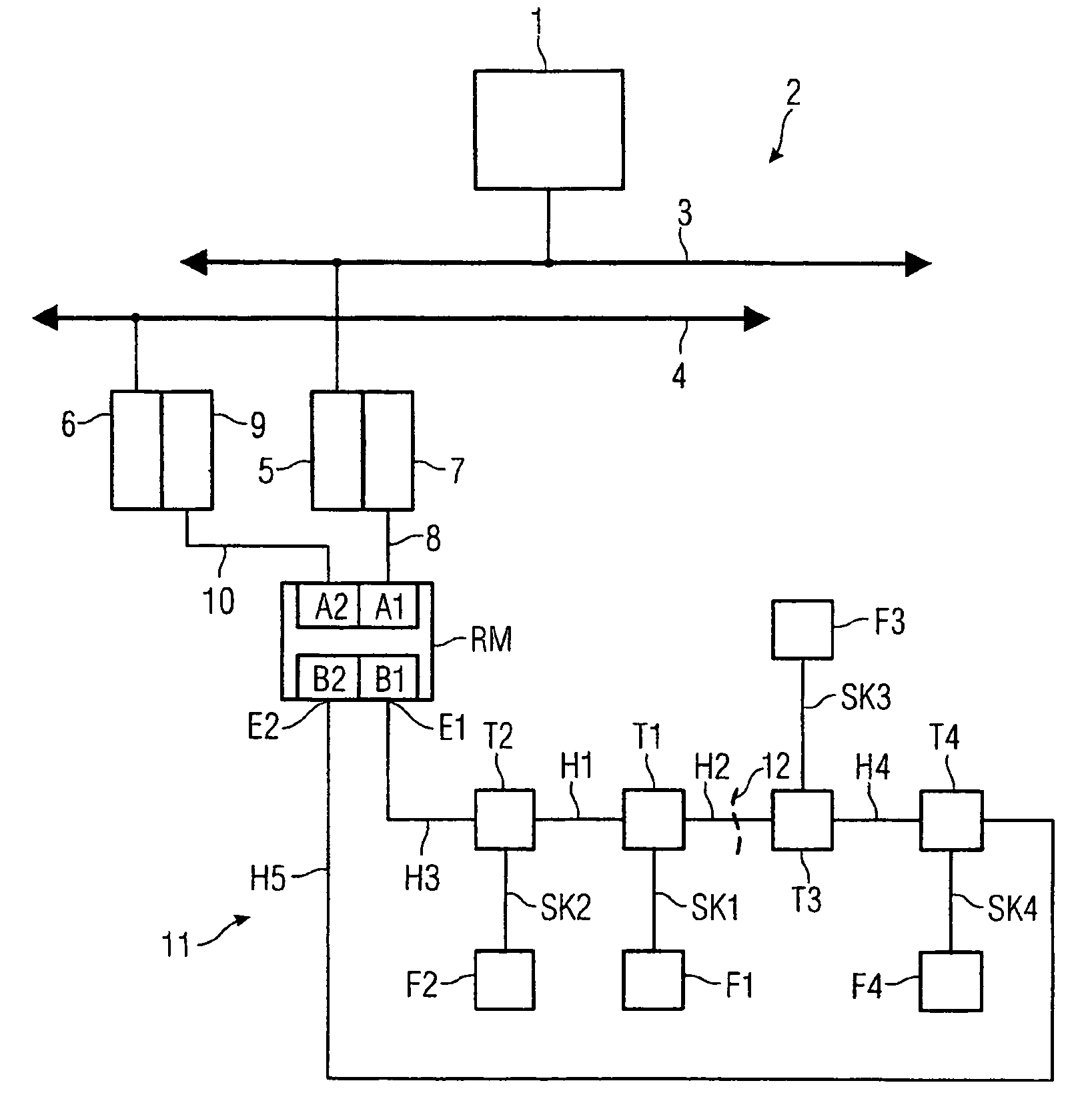
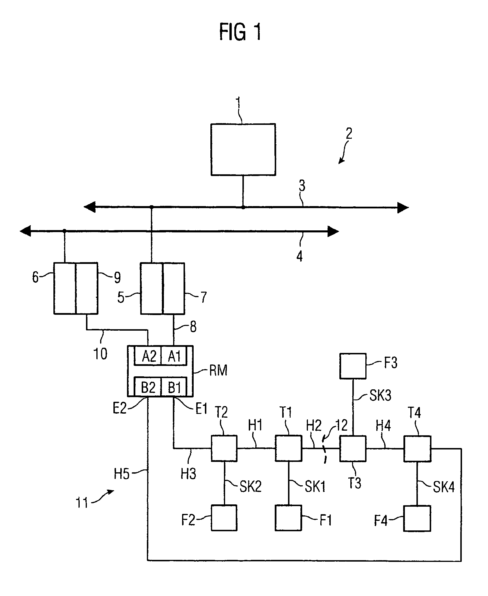
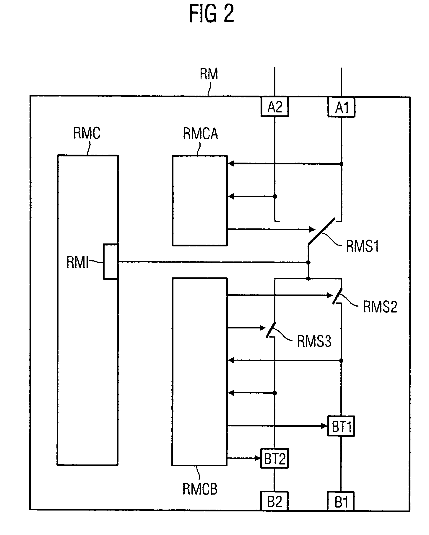
[0027]FIG. 1 shows a part of an automation technology system. A control system 1 is connected to a bus system 2 in accordance with the PROFIBUS DP Specification. The bus system 2 can be configured as a simple system, or to provide redundancy as shown here. At each of the two communication channels 3, 4 of the bus system 2, as well as other devices not shown here, for example automation units, a link 5 or 6 is connected in each case. The link 5 is linked to a segment coupler 7 which is connected via a drop cable 8 to a port A1 of a redundancy manager RM. The other link 6 is linked to a further segment coupler 9 which is connected via a further drop cable 10 to a port A2 of the redundancy manager RM. A network 11 which complies with the PROFIBUS PA specification and has a linear topology is connected to two further ports B1 and B2 of the redundancy manager RM. The one line end E1 of the network 11 is formed by the end of the trunk cable H3 connected to the port B1, which at its other ...


PUM


Abstract

The invention relates to a network, in particular a PA PROFIBUS network having redundant properties and a linear topology. Two line ends are connected to a redundancy manager which disconnects said line ends in error-free conditions and connects them in error conditions. Said redundancy manager supplies voltage to the first line end for operating customers' mobile telephones each of which is connected to the network by a branching unit. After receiving a supply voltage on one connection thereof, said branching units check the state of a cable which is connected to the other network connection and transmit the supply voltage in the faultless condition thereof only. When the redundancy manager does not detect the supply voltage on the other end of the line end at least during a predetermined space of time after voltage supply, said redundancy manager supplies the voltage thereto. A cable having a disturbance is then disconnected from the line by the adjacent branching units.

Description

CROSS REFERENCE TO RELATED APPLICATIONS[0001]This application claims priority to the German application No. 10356118.8, filed Nov. 27, 2003, to the German application No. 10 2004 055 53.0, filed Nov. 15, 2004 and to the International Application No. PCT / EP2004 / 013455, filed Nov. 26, 2004 which are incorporated by reference herein in their entirety.FIELD OF INVENTION[0002]The invention relates to a network, In particular a PA PROFIBUS network, with redundant properties, a branching element for a user device in said network, a redundancy manager for said network and a method for operating said network.BACKGROUND OF INVENTION[0003]In automation systems for manufacturing or process technology with “classic” wiring of field devices, for example measurement converters and / or control elements, in which the field devices are connected in each case via a 4-wire master cable and subdistributors by a separate pair of wires to a programmable logic controller, the failure of one of the field dev...

Claims


Application Information

Patent Timeline
Patent Type & Authority Patents(United States)
IPC IPC(8): G06F11/00G05B19/048H04L69/40
CPCG05B19/048H04L69/40G05B2219/24182G05B2219/25021
Inventor FEHRMANN, HOLGERGEIGER, FRIEDHELMHAMMER, GERHARDROTHER, KLAUS
Owner SIEMENS AG
Learn More