
Image processing device and method

a technology of image processing and image, applied in the field of image processing device and method, can solve the problems of correction accuracy, enormous burden on the user, and cost increase, and achieve the effect of high precision, easy color balance correction, and low cos

Inactive Publication Date: 2009-02-17
FUJIFILM BUSINESS INNOVATION CORP
View PDF15 Cites 48 Cited by
  • Summary
  • Abstract
  • Description
  • Claims
  • Application Information

AI Technical Summary

Benefits of technology

[0011]The present invention has been made in consideration of the above-described facts and provides an image processing device and an image processing method with which it is possible to conduct color balance correction easily and with high precision, without placing a burden on the user or increasing costs.
[0015]In this manner, in the first aspect of the invention, the color correction parameter corresponding to the color balance correction instructed via the instruction unit is read from the plural color correction parameters stored in advance in the storage unit, to thereby conduct color balance correction. Thus, it becomes unnecessary to use a test chart when conducting correction of difference in color balance resulting from differences in the machines and variations in environmental conditions. Thus, it is possible to prevent that costs, as a result of providing a colorimeter and / or preparing a separate scanner, increase. It is also possible to prevent that an enormous burden is placed on the user as a result of causing the user to conduct the operation of comparing individual patches on a test chart with color samples. Further, correction precision can be prevented from being controlled by the skill level of the user or temporal changes in color samples.
[0018]setting a plurality of moving target positions of a lightness axis or a gray axis on a uniform color space in color balance correction; storing in a storage unit, for the plurality of set moving target positions of the lightness axis or the gray axis, color correction parameters for performing color balance correction corresponding to moving the lightness axis or the gray axis substantially parallel to a specific moving target position on the uniform color space with respect to inputted color image data; and reading a color correction parameter corresponding to the instructed color balance correction among the plurality of the color correction parameters stored in the storage unit, to perform color balance correction with respect to color image data to be processed using the read color correction parameter when color balance correction with respect to the color image data to be processed is instructed via an instruction unit. Therefore, similar to the first aspect, it becomes possible to conduct color balance correction easily and with high precision without placing a burden on the user or increasing costs.

Problems solved by technology

However, although the correction of (1) can correct with high precision individual differences of printers, there is the problem that the cost increases because it is necessary to either dispose a colorimeter in the printer or prepare a separate scanner.
Also, because the work of comparing the patches with the sample, which requires skill, is left to the user, there are drawbacks in that an enormous burden is placed on the user and correction precision is largely dependent on the skill level of the user in regard to the work of the comparison.
There is also the problem that correction precision drops in accompaniment with changes in the sample over time.
With respect to the correction of (3), for example, in a case where the color conversion parameters are switched in accordance with environmental condition, it is necessary to prepare an environmental chamber for exposing the printer to various types of environmental conditions in order to obtain color conversion parameters corresponding to various types of environmental conditions, and there is the problem that this costs much and is troublesome.
Also, in a case where plural gamma coefficients are learned in advance by a neural net and the gamma coefficients are switched in accordance with toner characteristics, control for switching the parameters becomes extremely complex.

Method used


Image

  • Image processing device and method
  • Image processing device and method
  • Image processing device and method

Examples


Embodiment Construction

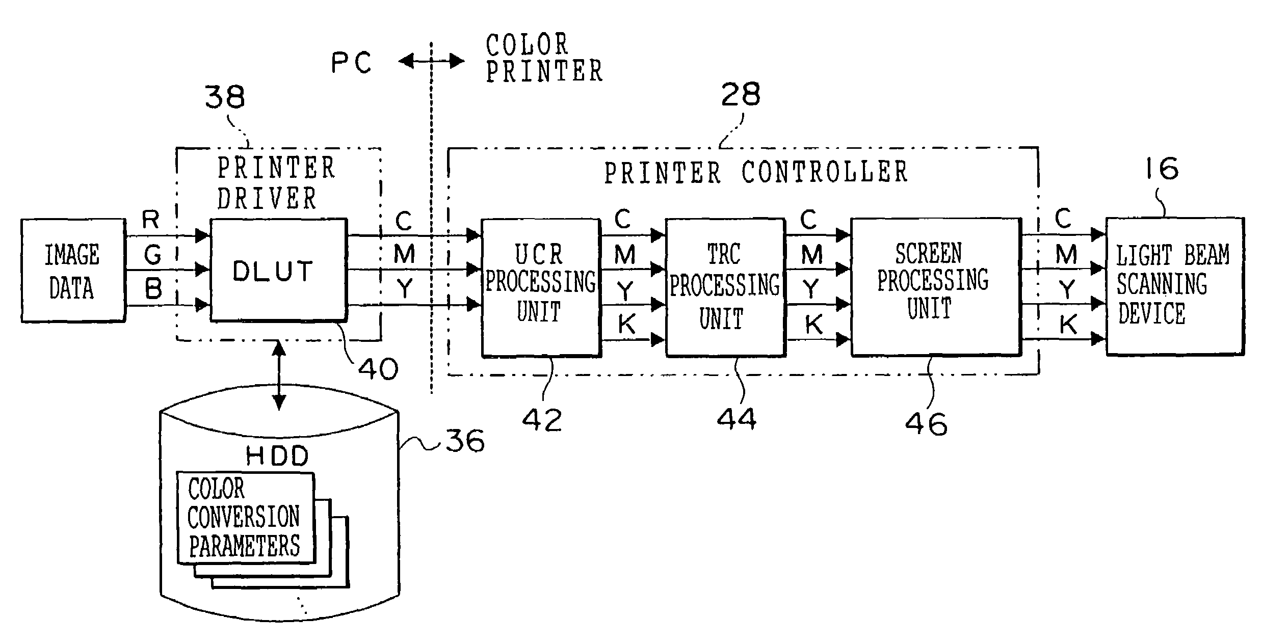
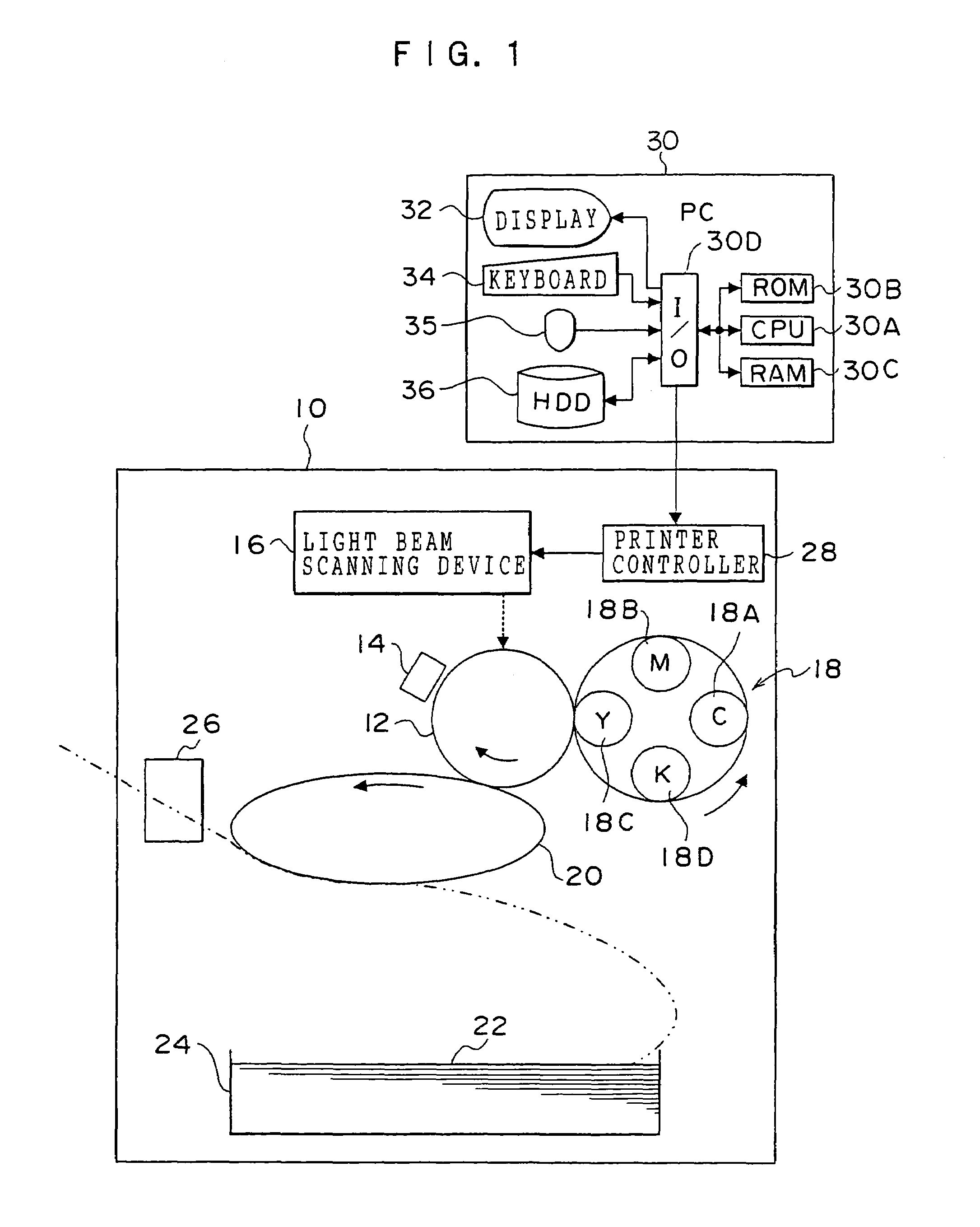
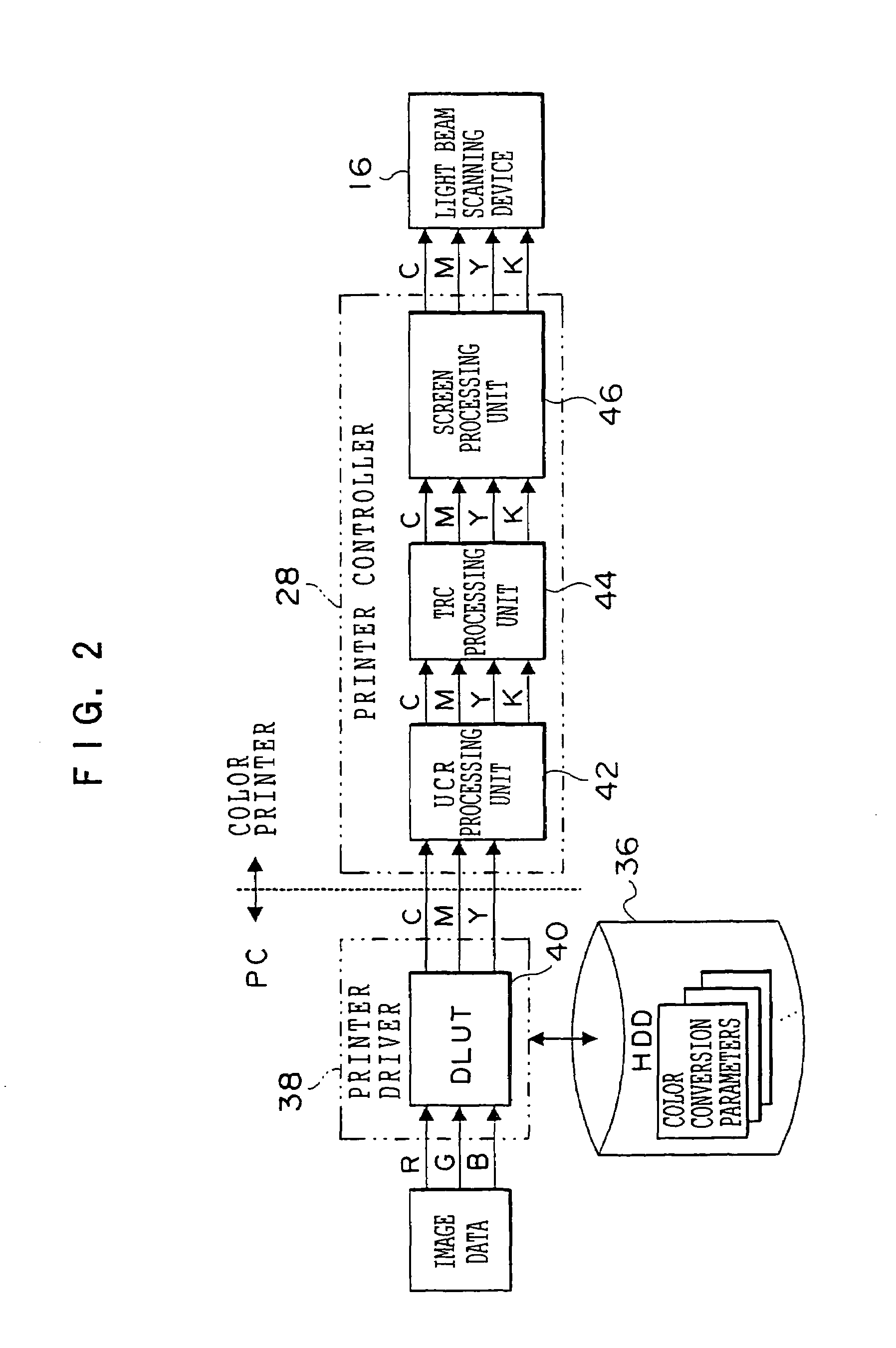
[0027]FIG. 1 shows a color printer 10 pertaining to the present embodiment and a computer (PC) 30 that is connected to the color printer 10. Although FIG. 1 shows an example where the number n of color printers 10 is one and the number m of PCs 30 is one, the numbers n and m may be plural (and it goes without saying that n and m do not have to be identical numbers).

[0028]The color printer 10 is disposed with a photosensitive drum 12 serving as an image carrier, and the photosensitive drum 12 is charged by a charger (electro static charging device) 14. A light beam scanning device 16 that emits laser beams, which are modulated in accordance with the image to be formed and are deflected along a main scanning direction (direction parallel to the axial line of the photosensitive drum 12), is disposed above the photosensitive drum 12. The laser beams emitted from the light beam scanning device 16 scan a peripheral surface of the photosensitive drum 12 in the main scanning direction, the ...


PUM


Abstract

An image processing device including a storage unit which stores, for set moving-target-positions of a lightness or gray axis on an uniform color space in color balance correction, color correction parameters for performing color balance correction corresponding to moving the lightness or gray axis substantially parallel to a specific moving-target-position on the uniform color space to inputted color image data, and a correction unit which, when color balance correction to the target color image data is instructed via an instruction unit, reads a color correction parameter corresponding to the instructed color balance correction among the color correction parameters stored in the storage unit, to perform color balance correction to the target color image data using the read color correction parameter, is provided.

Description

CROSS-REFERENCE TO RELATED APPLICATION[0001]This application claims priority under 35 USC 119 from Japanese Patent Application No. 2003-182666 the disclosures of which are incorporated by reference herein.BACKGROUND OF THE INVENTION[0002]1. Field of the Invention[0003]The present invention relates to an image processing device and method, and in particular to an image processing device and an image processing method that conduct color balance correction with respect to a color image.[0004]2. Description of the Related Art[0005]Among printers that form a color image, subtle differences arise in color tint (gray balance, etc.) of the image due to differences in the machines and variations in environmental conditions, even if the printers are of the same model. The following technologies are known as technologies that correct individual differences in color tint.(1) Correction Based on Colorimetric Processing[0006]A test chart is created in which numerous patches whose densities or col...

Claims


Application Information

Patent Timeline
Patent Type & Authority Patents(United States)
IPC IPC(8): G06F15/00B41J1/00B41J2/525G06K9/00G06T1/00H04N1/46H04N1/60
CPCH04N1/603
Inventor UNE, KIYOSHI
Owner FUJIFILM BUSINESS INNOVATION CORP
Learn More