
Chip tray loading device and process

a chip tray and loading device technology, applied in the field of casino management, can solve the problems of inability to automatically load the chip tray of the gaming table, the casino loses revenue, and the independent physical verification can be time-consuming and labor-intensive, and achieve the effect of reducing or eliminating the number of times

Inactive Publication Date: 2009-02-17
JCM AMERICAN CORP
View PDF38 Cites 13 Cited by
  • Summary
  • Abstract
  • Description
  • Claims
  • Application Information

AI Technical Summary

Benefits of technology

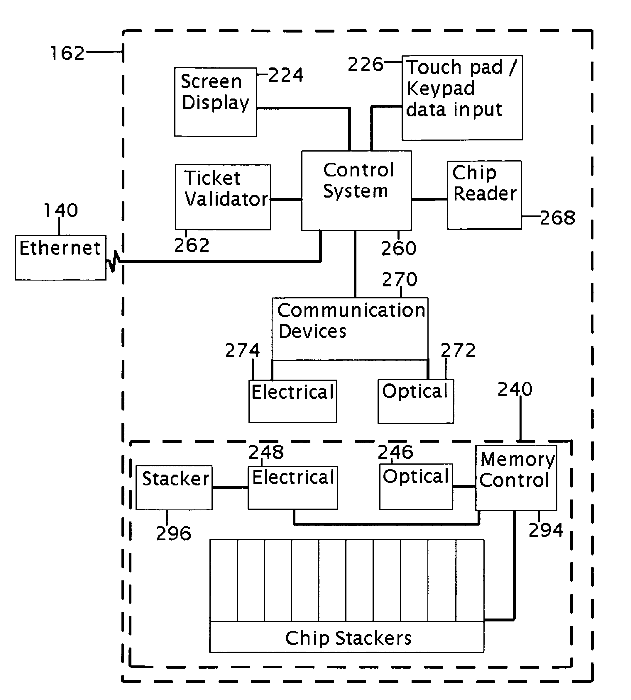
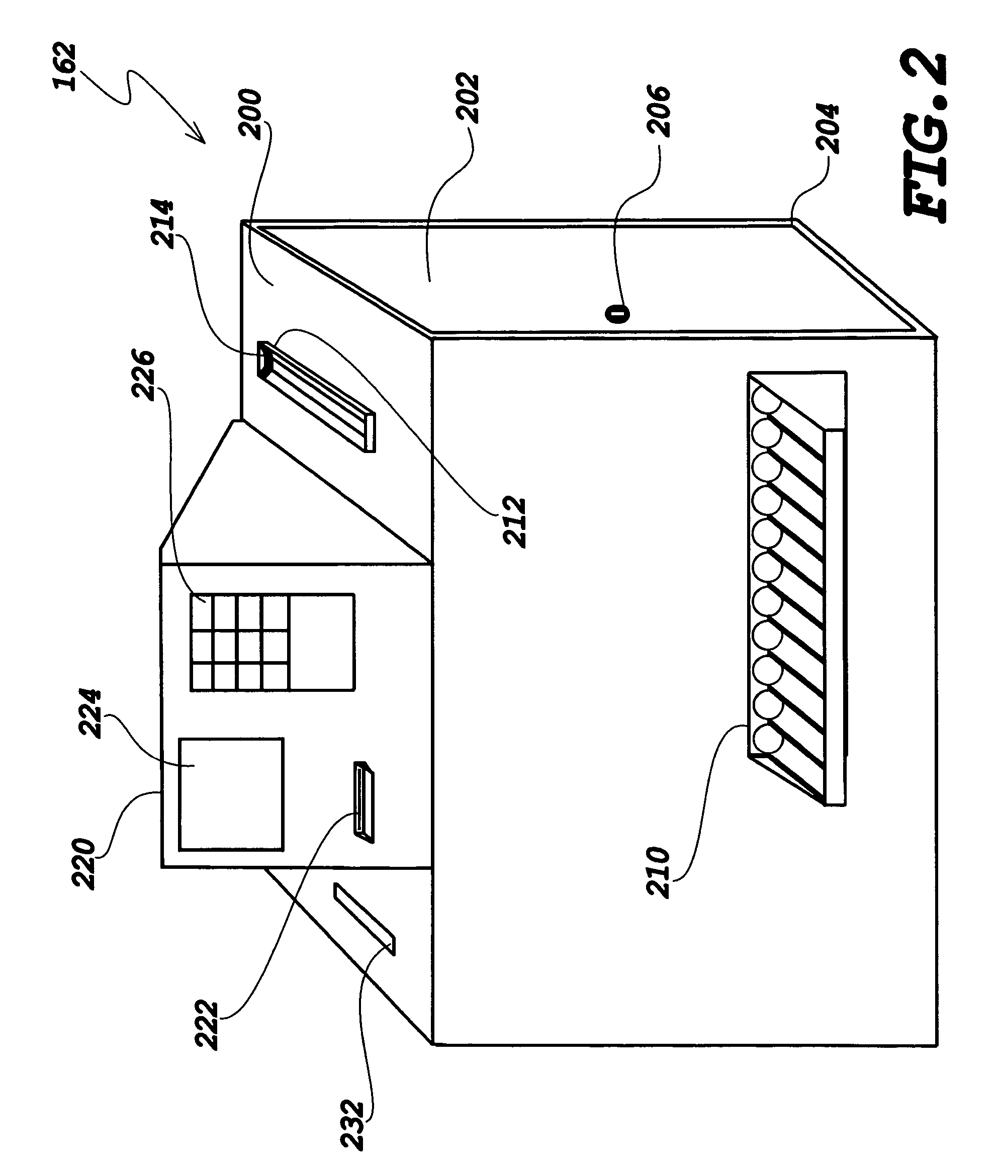
The present invention is about a chip dispensing kiosk that can hold a large number of casino chips and dispense them to pit managers or their designees at a work station. The kiosk is connected to the casino's accounting system to track the dispensing of chips. The kiosk can also provide secure storage and dispensing of event transaction documents that comply with regulations. The kiosk can be stocked with chips and can also provide secure storage and dispensing of event signals that allow for chip transfers between the kiosk and the tables or players in the pit area. The invention also includes a smaller chip tray loading device that can identify and sort chips, perform calculations, and load a removable gaming table chip tray.

Problems solved by technology

Such independent physical verifications can be time consuming and labor intensive.
Additionally most US casinos do not return the table chip trays to a standard chip tray bank value and / or chip denomination configuration upon opening or starting such a table's period of operation due to the time and labor required for reloading the chip tray to such a standard.
Restocking a gaming table during the course of play can be distracting to the players and cause the casinos to lose revenue if an impatient player must wait for additional casino chips to be delivered to the gaming table.
These existing devices do not automatically load a gaming table chip tray with a specified bank value and / or chip denomination configuration as previously described.

Method used


Image

  • Chip tray loading device and process
  • Chip tray loading device and process
  • Chip tray loading device and process

Examples


Embodiment Construction

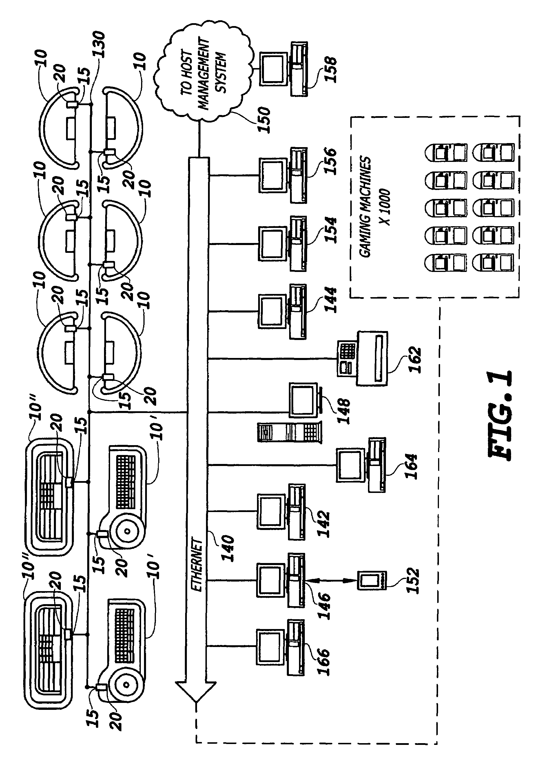
[0020]FIG. 1, schematically depicts multiple gaming tables 10 each having bill acceptors 20 that are interconnected over a low-level network 130 to an Ethernet 140. These bill acceptors 20 can function as a chip gaming station processor or one or more tables may optionally have separate gaming station processors 15 interconnected with the bill acceptors 20 and the low-level network 130. FIG. 1 shows six card tables 10, two roulette tables 10′ and two craps tables 10″, representing a discrete pit area. It is to be understood that any type and number of chip gaming station processors 15 or tables 10 can be arranged in a pit area and that multiple groups of tables, each group being overseen by a Pit Manager, may be positioned within the casino. A more detailed description of the components of the systems depicted in FIG. 1 can be found in U.S. patent application Ser. Nos. 10 / 941,316, and 10 / 081,756 now U.S. Pat. No. 6,745,887 herein incorporated by reference.

[0021]The Ethernet 140 may ...


PUM


Abstract

A chip dispensing kiosk including a vault for holding casino chips, a dispensing assembly for dispensing selected numbers of casino chips and security and input systems to allow a pit manager to access the kiosk and have the kiosk dispense selected numbers of chips. These chips may be dispensed individually, in stacks or automatically loaded into a table chip tray back module. The kiosk is interactive with the casino's accounting system so as to report the dispensing of casino chips or receipt of casino chips. One preferred embodiment consists of a casino back room, cage, or Pit area chip tray management device that can be utilized by casino personnel to physically accept and count dumped gaming chips, communicate information with an ICT Intelligent Chip Tray Module, and automatically reload the chip tray per computer controlled specifications for any given table ID or chip loading requirement.

Description

[0001]This application is a Continuation In Part of U.S. application Ser. No. 11 / 202,304, filed on Aug. 11, 2005, entitled Inventory Manager—Chip Kiosk.BACKGROUND OF THE INVENTION[0002]1. Field of the Invention[0003]The present invention is generally directed to the field of casino management and in particular to a device and process whereby casino chips can be automatically sorted and loaded into trays to provide a supply of casino chip trays to gaming stations within a select area of the casino. In one embodiment, the invention contemplates a sorting, stacking and loading device that loads a chip tray to exact specifications corresponding to various programmable or selectable chip denomination configurations.[0004]2. General Background and State of the Art[0005]Modern casinos have evolved to incorporate hundreds or thousands of slot machines or other types of coin or ticket operated gaming machines. However, gaming tables where players can play blackjack, poker games, roulette or ...

Claims


Application Information

Patent Timeline
Patent Type & Authority Patents(United States)
IPC IPC(8): A63B71/00
CPCG07F17/32
Inventor MATHIS, GWEN D.BUDDING, EWOUD A.
Owner JCM AMERICAN CORP
Learn More