
Drilling, perforating and formation analysis

a technology of perforation and formation analysis, applied in the field of drilling and completing a well, can solve the problems of negative skin of perforation, obvious safety, transportation and security issues, known perforation techniques, drilling techniques, etc., and achieve the effect of increasing permeability and negative skin

Active Publication Date: 2009-02-17
HALLIBURTON ENERGY SERVICES INC
View PDF109 Cites 109 Cited by
  • Summary
  • Abstract
  • Description
  • Claims
  • Application Information

AI Technical Summary

Benefits of technology

The present patent is about a system and method for drilling and perforating a well bore using a laser beam to remove material and perform analysis without removing the laser beam from the well bore. The laser beam can be directed to remove material in multiple locations simultaneously or in different time intervals. The laser beam can be directed to heat material to emit light, which can be analyzed using laser induced breakdown spectroscopy. The laser beam can also be directed to remove debris and clean the surface of the well bore. The system includes a laser device, a laser directing device, a spectroscopy device, and an emitted light receiver. The technical effects of the patent include improved well bore analysis and drilling with reduced material removal.

Problems solved by technology

Both techniques, however, may result in a perforation having a positive skin, i.e. localized decreased permeability that reduces the production of formation fluid from the formation into the perforation.
In addition, these traditional perforating methods rely on the use of explosives, which pose obvious safety, transportation and security issues.
Known perforating techniques, as well as drilling techniques, do not provide any analysis of the formation rock being perforated or drilled.
More so, there is no known technique for analyzing the chemical elements and certain other chemical characteristics of formation rock in situ, that is, without removing the rock from the well.
Depending on whether the analysis can be performed on site, such analysis may add days or even weeks to the well completion.

Method used


Image

  • Drilling, perforating and formation analysis
  • Drilling, perforating and formation analysis
  • Drilling, perforating and formation analysis

Examples


Embodiment Construction

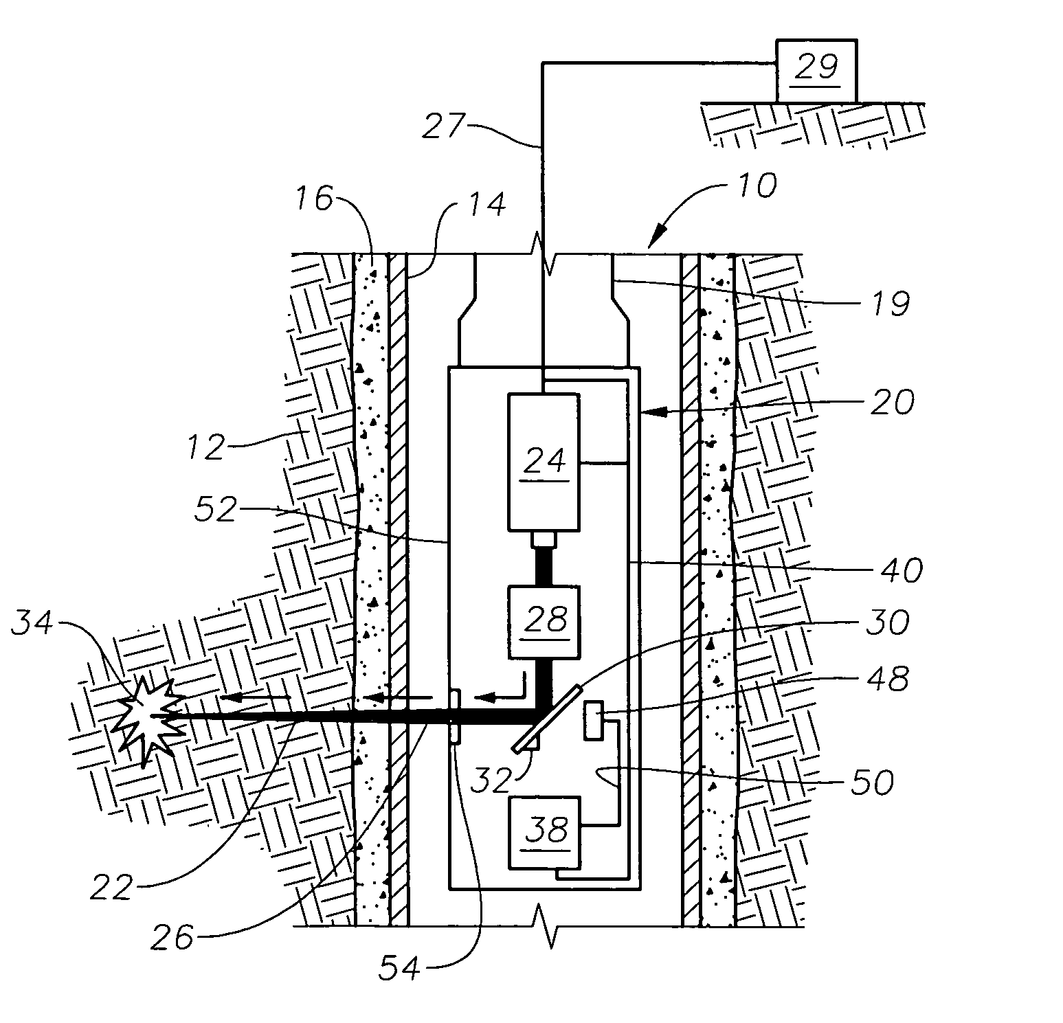
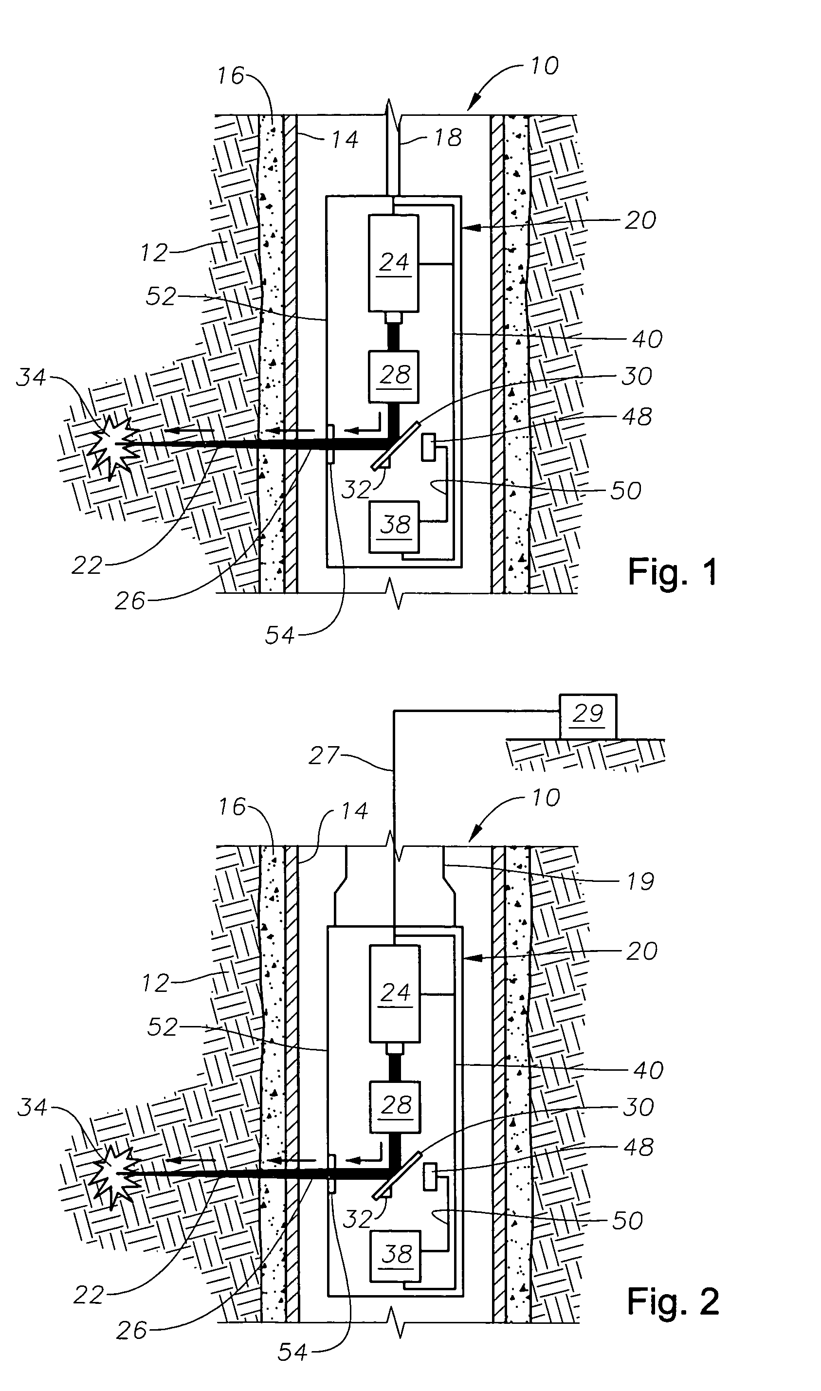
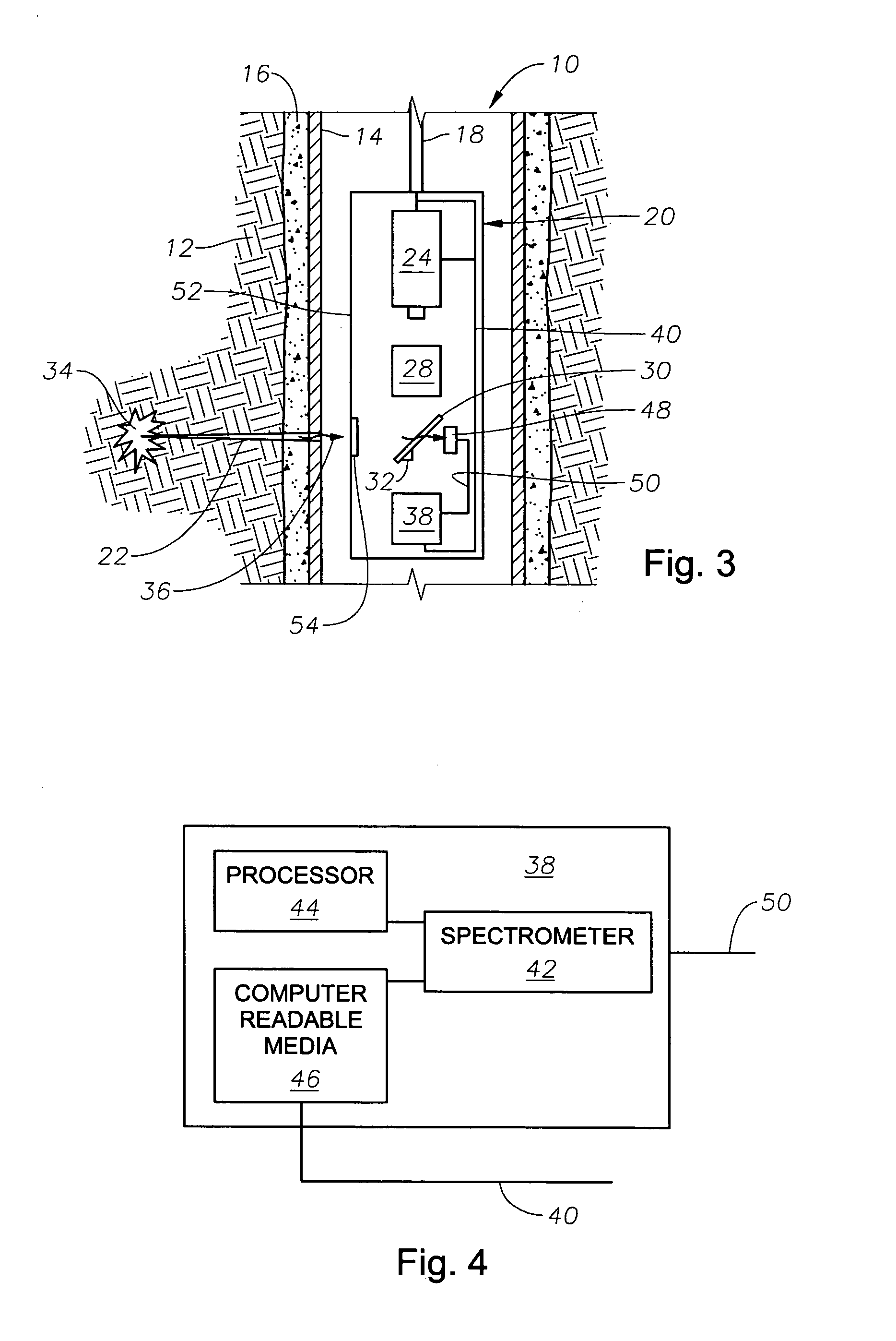
[0047]Referring to FIGS. 1 and 2, a cased well bore 10 in a formation 12 has a casing 14 affixed therein. A layer of cement or similar material 16 fills an annulus between the casing 14 and the well bore 10. An illustrative laser tool 20 constructed in accordance with the invention is depicted in use perforating the well bore 10. The illustrative laser tool 20 is adapted to be inserted into the well bore 10 depending from a wireline 18 (FIG. 1) or a tubing string 19 (FIG. 2), and direct a laser beam 26. Although depicted as removing material from the formation 12 to form a perforation 22, the laser tool 20 can be adapted to also or alternatively drill a new well bore, extend an existing well bore, or heat material to emit light for use in laser induced breakdown spectroscopy (LIBS). As the illustrative laser tool 20 of FIGS. 1 and 2 is depicted perforating a cased well bore 10, it is directing the laser beam 26 onto the casing 14, the cement 16 and the formation 12. The illustrative...


PUM

PropertyMeasurementUnit
time intervalsaaaaaaaaaa
angleaaaaaaaaaa
specific heataaaaaaaaaa

Abstract

A system and method of drilling and / or perforating uses a laser beam to remove material, such as to perforate the casing, cement and formation or drill a well bore. The system and method can further or alternately encompass material analysis that can be performed without removing the material from the well bore. The analysis can be performed apart from or in connection with drilling operations and / or perforating the casing, cement and formation. The analysis can be used in a feed back loop to adjust material removal, adjust material analysis, determine the location of future material removal, and for other uses.

Description

TECHNICAL FIELD[0001]The present disclosure relates generally to drilling and completing a well in an earth formation, and more specifically, to systems and methods for drilling, perforating, and analyzing the earth formation.BACKGROUND OF THE INVENTION[0002]Once a well bore has been drilled and one or more zones of interest have been reached, a well casing is run into the well bore and is set in place by injecting cement or other material into the annulus between the casing and the well bore. The casing, cement and formation are then perforated to enable flow of fluid from the formation into the interior of the casing.[0003]In the past, the casing, cement and formation have been perforated using bullets or shaped charges. Both techniques, however, may result in a perforation having a positive skin, i.e. localized decreased permeability that reduces the production of formation fluid from the formation into the perforation. It is generally desirable that the perforations have a neutr...

Claims


Application Information

Patent Timeline
Patent Type & Authority Patents(United States)
IPC IPC(8): E21B36/00E21B47/00E21BE21B7/15E21B36/04E21B43/11E21B49/00E21B49/06E21B49/10G01N21/71
CPCE21B7/15E21B36/04E21B43/11E21B49/00E21B49/06E21B49/10G01N21/718G01N21/954B23K26/0807B23K26/082E21B47/00E21B49/005
Inventor SKINNER, NEAL G.SMITH, JR., HARRY D.JONES, CHRISTOPHER M.GLEITMAN, DANIEL D.PELLETIER, MICHAEL T
Owner HALLIBURTON ENERGY SERVICES INC
Learn More