
Dynamic transmit power configuration system for wireless network environments

a wireless network environment and dynamic transmission technology, applied in the field of wireless computer networks, can solve the problems of inability to detect collisions in this manner, time-consuming and expensive site surveys, and inability to respond to periodic or subsequent changes

Inactive Publication Date: 2009-02-10
CISCO TECH INC
View PDF117 Cites 8 Cited by
  • Summary
  • Abstract
  • Description
  • Claims
  • Application Information

AI Technical Summary

Benefits of technology

[0010]The present invention provides methods, apparatuses and systems facilitating the configuration of transmit power and coverage areas corresponding to access points in a wireless network environment. The present invention in one embodiment facilitates the dynamic configuration of coverage boundaries across a plurality of access points, improving the performance of the wireless network environment.

Problems solved by technology

Such site surveys, however, are time consuming and expensive.
In addition, the analysis of the wireless network environment is performed with data gathered at a single point in time and, therefore, is not responsive to periodic or subsequent changes associated with the wireless network environment (such as deployment of new access points, or intermittent sources of RF interference, etc.).
In a WLAN, collision detection in this manner is not possible due to what is known as the “near / far” problem: to detect a collision, a station must be able to transmit and listen at the same time.
CSMA / CA also handles other interference and radio-wave related problems effectively, but creates considerable overhead.
The administrative or management functionality associated with WLAN networks, however, generally lacks an integrated and / or automated means of adjusting transmit power of access points to optimize WLAN performance.
Accordingly, many WLANs do not perform at optimum speed due to overlapping coverage areas and channel interference.

Method used


Image

  • Dynamic transmit power configuration system for wireless network environments
  • Dynamic transmit power configuration system for wireless network environments
  • Dynamic transmit power configuration system for wireless network environments

Examples


Embodiment Construction

A. Operating Environment

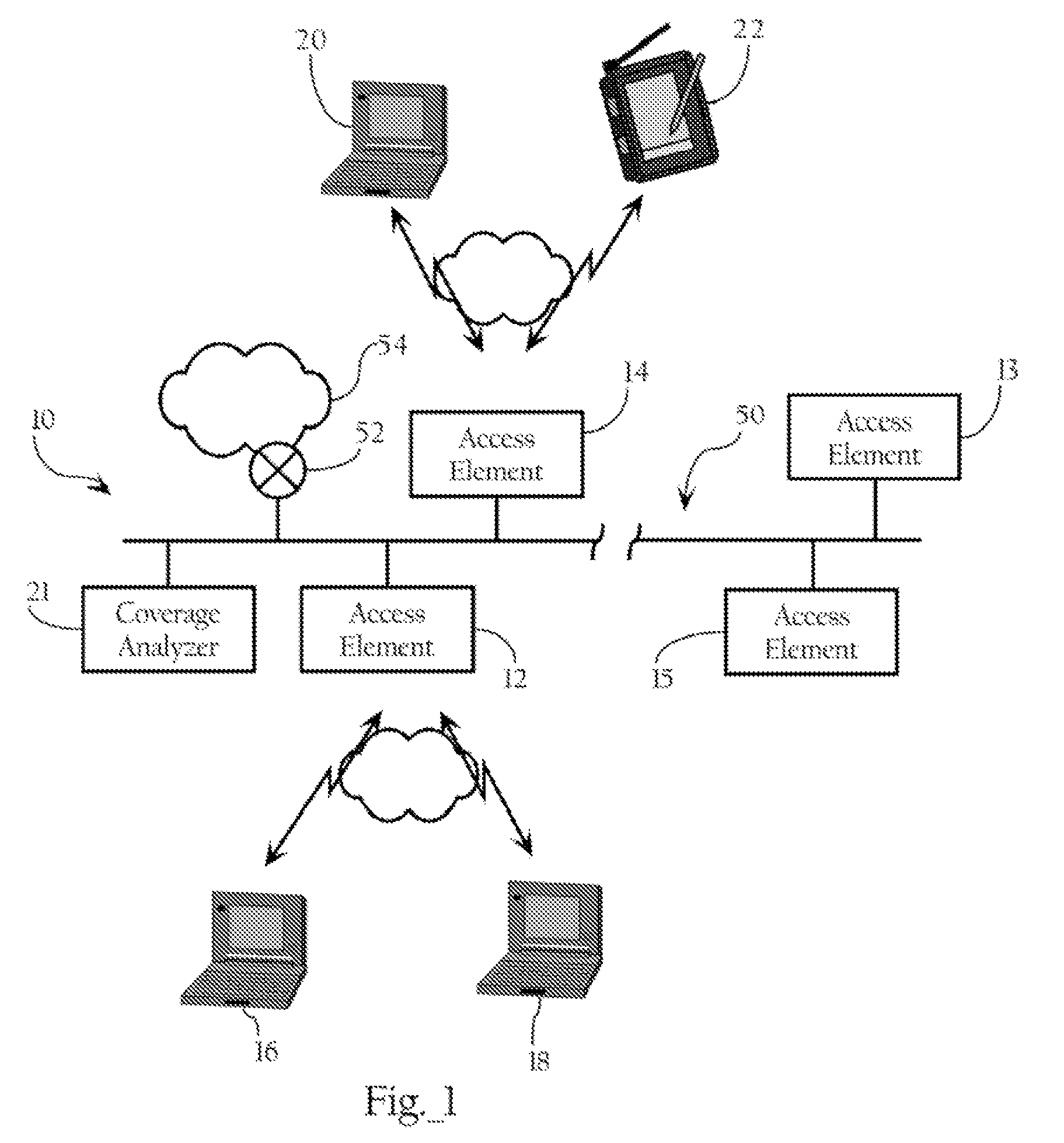
[0019]FIG. 1 illustrates a computer network environment including dynamic transmit power configuration functionality according to an embodiment of the present invention. The computer network environment depicted in FIG. 1 includes access elements 12, 13, 14, 15 deployed across wide area network 50 comprising a plurality of local area network segments 10. In one embodiment, the present invention further includes coverage analyzer 21 to receive coverage data from access elements 12, 13, 14, 15 and process the coverage data to compute transmit power levels for the access elements to optimize the performance of the wireless network environment, as described below.

[0020]The access elements, such as access elements 12, 14, are operative to establish wireless connections with remote client elements, such as remote client elements 16, 18, 20 and 22. The access elements can operate to bridge wireless traffic between the remote client elements and a wired computer netw...


PUM


Abstract

Methods, apparatuses and systems facilitating the configuration of transmit power and coverage areas corresponding to access points in a wireless network environment. The present invention in one embodiment facilitates the dynamic configuration of coverage boundaries across a plurality of access points, improving the performance of the wireless network environment.

Description

CROSS-REFERENCE TO RELATED APPLICATIONS[0001]The present application claims priority from U.S. patent application Ser. No. 10 / 407,372 filed on Apr. 4, 2003 which is entitled “Dynamic Transmit Power Configuration System for Wireless Networks Environments” which is herein incorporated by reference.[0002]This application makes reference to the following commonly owned U.S. patent applications and / or patents, which are incorporated herein by reference in their entirety for all purposes:[0003]U.S. patent application Ser. No. 10 / 165,938 in the name of Patrice R. Calhoun, Robert B. O'Hara, Jr. and Robert J. Friday, entitled “Method and System for Hierarchical Processing of Protocol Information in a Wireless LAN.”FIELD OF THE INVENTION[0004]The present invention relates to wireless computer networks and, more particularly, to methods, apparatuses and systems facilitating configuration of transmit power in a wireless network environment comprising a plurality of wireless, access points.BACKG...

Claims


Application Information

Patent Timeline
Patent Type & Authority Patents(United States)
IPC IPC(8): H04W4/00H04W24/00H04W48/16H04W52/24H04W52/34H04W88/08
CPCH04B17/318H04W52/34H04W52/245H04W24/00H04W48/16H04W88/08
Inventor HILLS, ALEXANDER H.DIETRICH, PAUL F.FRIDAY, ROBERT J.
Owner CISCO TECH INC
Learn More