
Interlocking frame system for floor and wall structures

a technology of interlocking frames and floor and wall structures, applied in the direction of walls, resiliently-mounted floors, flooring, etc., can solve the problems of advan systems, advan systems, and advan systems, and achieve the effect of providing lateral stability to tiles

Inactive Publication Date: 2009-02-10
WANG DENNIS H
View PDF36 Cites 52 Cited by
  • Summary
  • Abstract
  • Description
  • Claims
  • Application Information

AI Technical Summary

Benefits of technology

The system provides a stable, versatile, and drainage-friendly solution that allows for easy installation and removal of tiles without affecting the existing surface, offering flexible design options and preventing lateral movement of tiles.

Problems solved by technology

However, removing or demolishing an existing floor requires more work than a typical home do-it-yourselfer can do, not to mention the expertise needed for the drainage system.
The ADVAN system, however, still has its drawbacks.
First, since each frame is a flat structure with legs and bosses at the bottom, the tiles tend to shift sideways even after they are glued to the frame.
Such gaps cannot be filled by grouting, since it would affect the drainage design, as well as cause the tiles to crack.
In many applications, when the frame is trimmed to fit a certain dimension, no interconnection points are left, thus limiting the versatility of the frame.
This system discloses an interconnected flooring system, which does not provide for support of the tiles or panels.
Nor does it provide for varying tile designs from frame to frame.

Method used


Image

  • Interlocking frame system for floor and wall structures
  • Interlocking frame system for floor and wall structures
  • Interlocking frame system for floor and wall structures

Examples


Embodiment Construction

[0025]An interlocking modular frame system for floor and wall tiles is disclosed.

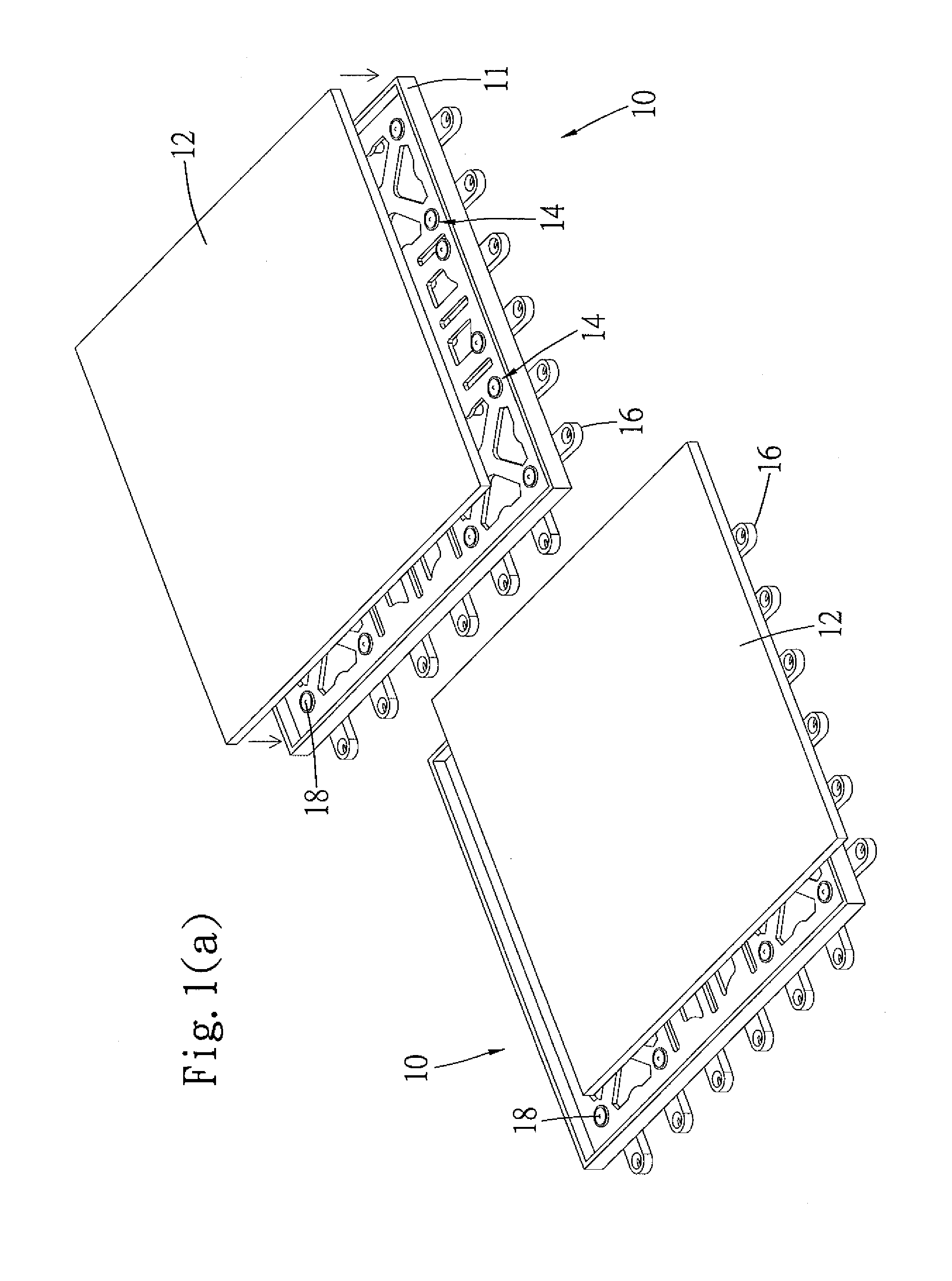
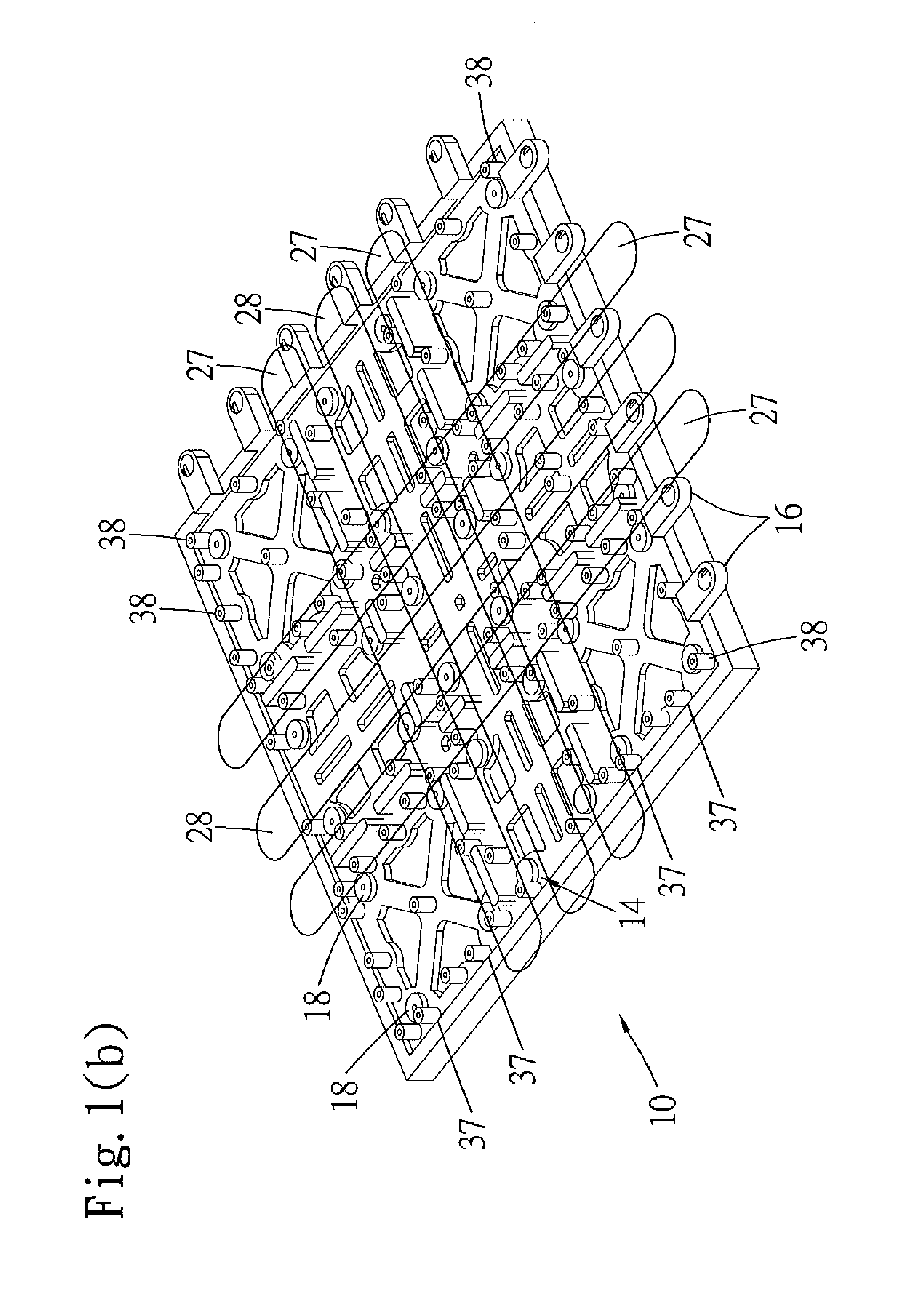
[0026]Reference is first to FIG. 1 (a), where two modular frames 10 in accordance with the present invention is shown. The frames 10 can be interconnected by coupling the bosses 16 on one edge of one frame to the legs 37 (not shown) underneath the other frame. The frame 10 has a planar member with a raised edge 11 around its perimeter, thus forming a “tray-shaped” structure for supporting the tile 12. Glue holes 14 with overflow are dispersed throughout the surface of the frame 10, which can be filled with adhesive material that will bond to the tile 12 when it is in place. Nail or screw holes 18 may also be provided for attaching the frame 10 to the ground or to the wall, whatever the intended design is. For installation, the frames may be first placed over an area to be covered. Tiles of various designs or dimensions may then be applied to the frames using adhesives.

[0027]As can be appreciated, since ...


PUM

PropertyMeasurementUnit
perimeteraaaaaaaaaa
lengthaaaaaaaaaa
heightaaaaaaaaaa

Abstract

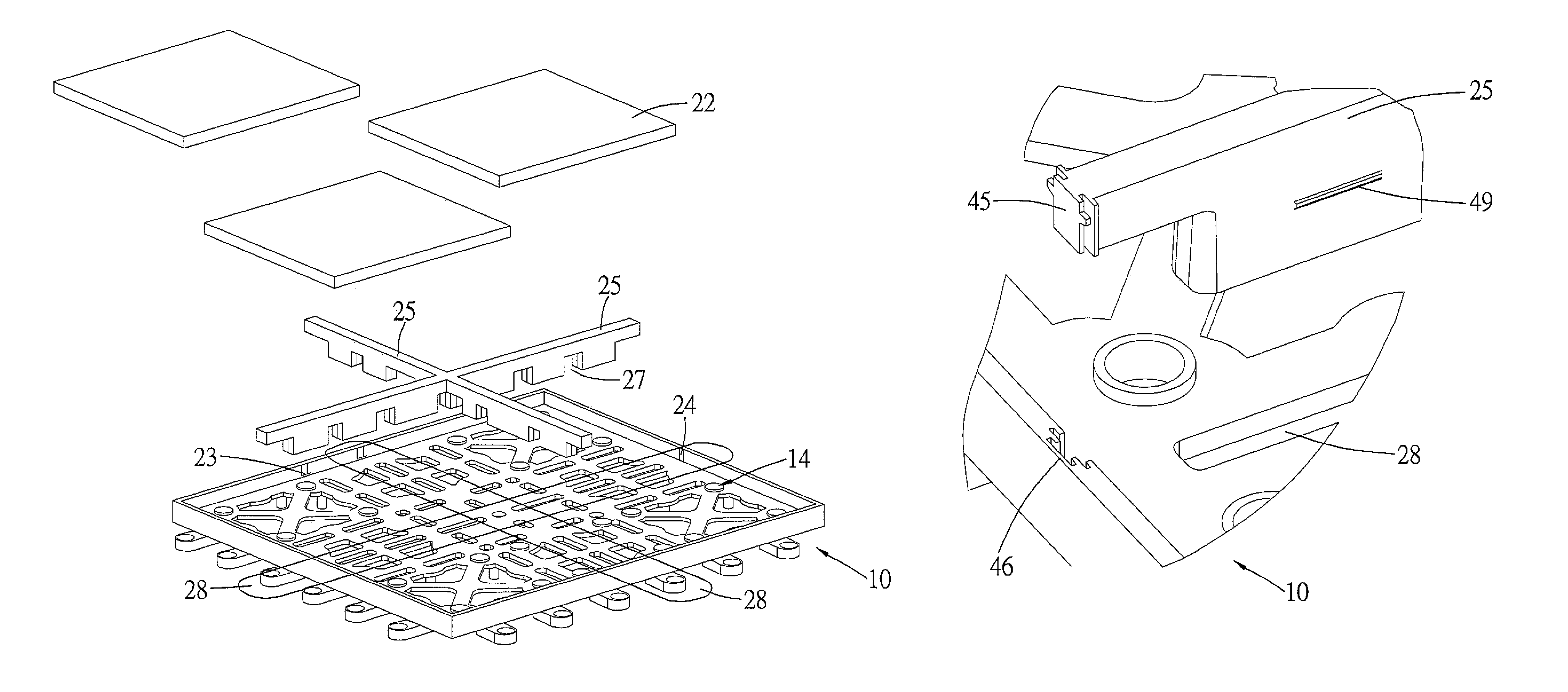
A frame for an interlocking system for floor or wall tiles has a base frame with a lid surrounding its perimeter. The lid serves to fill the gap between frames after the tiles are installed, as well as provide lateral stability to the tiles. The bottom of the base frame has an array or grid of support legs. On at least one side of the perimeter, the base frame has a plurality of bosses or slotted connectors extending outwardly from the base frame, which can be used to make connection with the support legs of another base frame. A filler, or divider, frame, of a given shape, e.g. “+” or “#”, is used to guide the placement of the tiles onto the base frame, as well as fill the gap between the tiles. Notches are formed on the base frame to securely engage the filler frame. One set of notches are formed through the surface of the base frame's planar body, white the other set of notches are formed on the inside surface of the lid of the base frame.

Description

PRIORITY CLAIM[0001]This patent application claims priority under 35 U.S.C. Sec. 119 (e) Provisional Patent Application No. 60 / 681,837, filed on May 17, 2005, the contents of which are incorporated herein by reference.FIELD OF THE INVENTION[0002]The present invention relates to the field of modular floor tiles and modular floor tile systems, and more particularly relates to flexible inter-connectable modular floor or wall tiles systems. The system may be designed as a floor covering for a patio, a deck, a garage, an exterior room or even an interior room, all without affecting the existing drainage system. More particularly, the system may be designed as a wall covering, thus allowing different tile or paneling designs.BACKGROUND OF THE INVENTION[0003]Modular floor tiles have become more popular, as homeowners find it easier to remodel or extend their living spaces using commonly available tools. For example, to remodel or repair an existing patio floor, it may be necessary to remov...

Claims


Application Information

Patent Timeline
Patent Type & Authority Patents(United States)
IPC IPC(8): E04F15/00E04B2/00E04F13/08E04F15/22
CPCE04F13/0862E04F13/142E04F15/02E04F15/022E04F15/043E04F15/02194E04F15/087E04F15/105
Inventor WANG, DENNIS H.
Owner WANG DENNIS H
Learn More