Cutting machine for tyre

A cutting machine and tire technology, applied in metal processing and other directions, can solve the problems of non-parallel ends, affecting tire test pieces, and high production costs, and achieve the effects of low cutting cost, long service life, and low high-speed cutting wear.

Active Publication Date: 2012-07-04
尹家旺
View PDF1 Cites 1 Cited by
  • Summary
  • Abstract
  • Description
  • Claims
  • Application Information

AI Technical Summary

Problems solved by technology

[0004] In order to solve the disadvantages of cutting tires with a toothed saw blade in the prior art, the saw blade is easy to wear, the cutting time is long, the service life is short, the production cost is extremely high, the end face breaks the steel wire, the surface is rough, the two end faces are not parallel, and the tire test piece is affected. The present invention provides a tire cutting machine with a simple structure. The cutting machine adopts two diamond knife belts, the service life is twice that of the traditional band saw, the cutting time is 1 / 8 of the traditional process, and the total cost is 1 / 8 of the traditional process. 1 / 2

Method used


Image

  • Cutting machine for tyre
  • Cutting machine for tyre

Examples


Embodiment Construction

[0013] The present invention will be further described below in conjunction with drawings and embodiments.

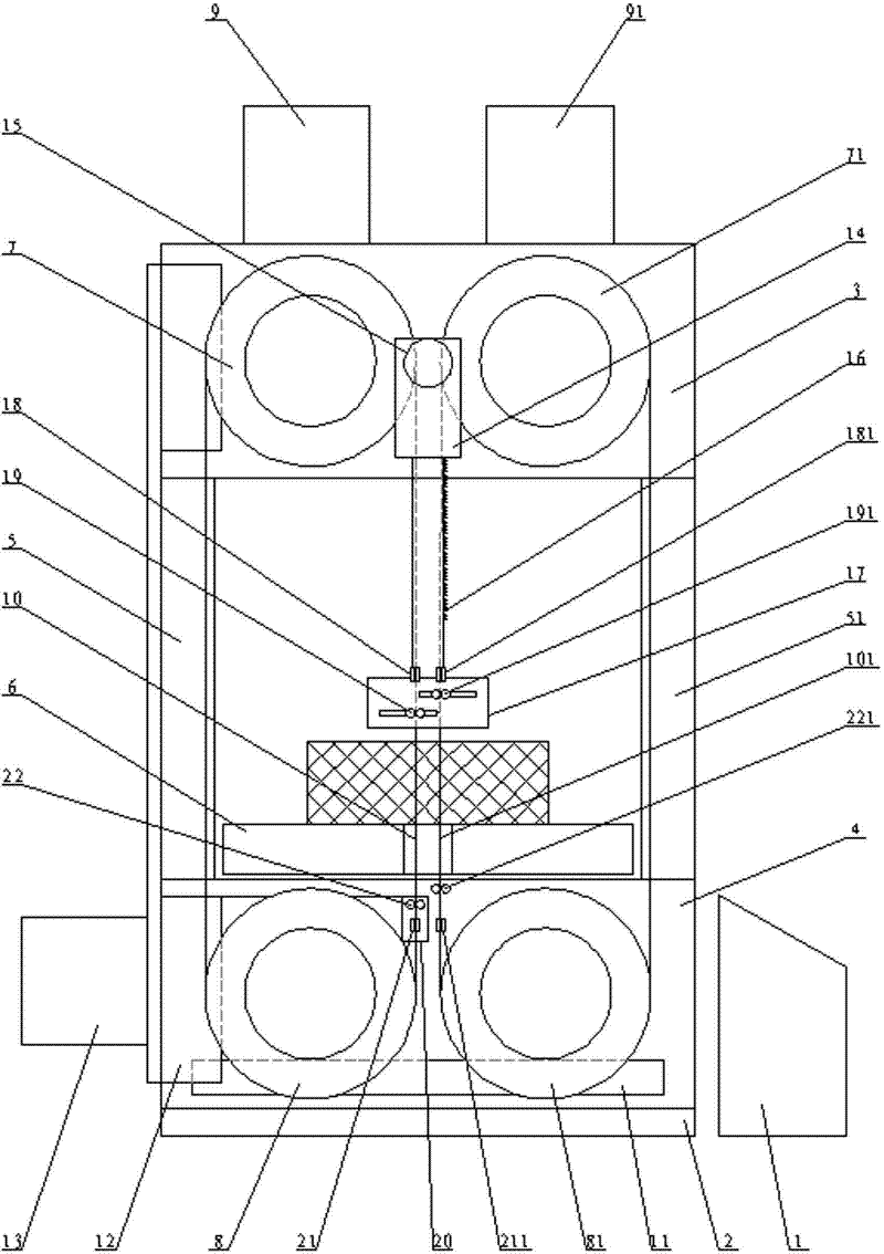
[0014] figure 1 As shown, the tire cutting machine mainly includes an electric control box 1, a machine base 2, an upper frame 3, a lower frame 4, a left protective frame 5, a right protective frame 51, a left driving wheel 7, a right driving wheel 71, and a left driven wheel 8, right driven wheel 81, left drive motor 9, right drive motor 91, left cutter belt 10, right cutter belt 101 and workbench 6. The base 2 is provided with a lower frame 4, the two sides of the lower frame 4 respectively support the upper frame 3 through the left and right protective frames 5, 51, and the workbench 6 is movably arranged on the lower part of the left and right protective frames 5, 51. The frame 4 is in a state of lifting and tilting. The workbench 6 is connected with a high-speed feed motor and a slow feed motor through a shift clutch. The shift clutch is connected with the electri...


PUM


Abstract

The invention relates to a cutting machine for a tyre, mainly comprising an electric control box, a machine base, a stand and a work table, wherein the stand is arranged on the machine base; the work table is arranged in the stand; the stand is internally provided with a left knife belt transmission device and a right knife belt transmission device which are connected with the electric control box; and the left knife belt transmission device and the right knife belt transmission device are both provided with knife belts penetrating through the work table. In the cutting machine disclosed by the invention, the left knife belt transmission device and the right knife belt transmission device are adopted to respectively drive two toothless knife belts to form tyre test pieces by carrying out one-time cutting on the tyre, and the cutting of the tyre test pieces with different specifications, thicknesses and sizes is realized by matching with a knife belt regulating device. The cutting machine has the advantages of simple and compact structure, usage safety of the cutting knife belts, long service life, low cutting cost, smooth cutting section of the tyre, cutting regularity of steel cords, accurate size of the tyre test pieces, accurate testing performance of the tyre test pieces and wide application scope.

Description

technical field [0001] The invention relates to a tire cutting machine, specifically a kind of machine which uses two toothless knife belts to cut various automobile tires synchronously, and simultaneously takes out double-end rubber blocks for the technical department to detect the inner quality of the tires. Background technique [0002] With the rapid development of the automobile industry, all-steel radial tires have become the focus of the development of the tire industry. The quality of the tires is a common concern of users. Physical and chemical tests were carried out on the distribution and binding surface. The traditional use of grinding wheel cutting machine to cut the section will cause local high-temperature carbonization, the section will be sticky, and the physical properties will change. Besides, the rotational speed of the emery wheel is very high during cutting, which easily damages the emery wheel cutting piece, has poor safety, produces peculiar smel...

Claims


Application Information

Patent Timeline
Patent Type & Authority Patents(China)
IPC IPC(8): B26D1/46B26D7/26B26D5/08B26D7/22
Inventor 尹家旺
Owner 尹家旺
Why Eureka
Try Eureka