
Work comfort evaluating device and work comfort evaluating method

a technology of work comfort and evaluating device, which is applied in the field of work comfort evaluating device and work comfort evaluating method, can solve the problems of large physical load on the steering wheel, erroneous judgment of driving large physical load on the driver, so as to evaluate the level of work comfort and work comfort

Inactive Publication Date: 2009-02-03
THE YOKOHAMA RUBBER CO LTD
View PDF15 Cites 3 Cited by
  • Summary
  • Abstract
  • Description
  • Claims
  • Application Information

AI Technical Summary

Benefits of technology

The present invention provides a work comfort evaluating device and method for evaluating a level of comfort of work by measuring myoelectric potentials of muscles when the work is done by antagonistic activities of the muscles. The device includes a pair of detecting sensors, an amplifier, a signal processing part, a work load intensity calculating part, and an evaluation part. The method involves calculating a synchronous contraction intensity of the muscles, calculating a level of work load intensity in the work, and evaluating the level of comfort of the work by normalizing the synchronous contraction intensity with the work load intensity. This allows for a quantitative evaluation of work comfort from short-time measurement results. The invention can be used for evaluating various works, such as driving a vehicle, and provides a faster and more accurate way to evaluate work comfort compared to conventional methods.

Problems solved by technology

If the data of the previous driving is used, which contains the myoelectric potential level that is probably different from the level of the current measurement, the judgment of the driving load on the driver will be erroneous.
Accordingly, if the threshold value is determined by multiplying the conflict feature quantity for calibration by a fixed coefficient, judgment of the driving load on the driver will be erroneous.
Accordingly, in a case where a large steering force is required for operating the steering wheel depending on the type of tires mounted, the physical load imparted to the steering wheel is large and the driving load increases.
However, the increase of the steering force results in an increase of the driving load.
Therefore, it is impossible to know a difference of the driving load caused by the mental burden on the drive in the high-speed cruising mode from the mental load in the highway congestion mode.
Such problems also occur not only in the evaluation of the steering operation of the vehicle but also in a case where a comfort is evaluated at work where an object to be operated is operated by antagonistically activating plural muscles (a pair of muscles, for example) of a human body.

Method used


Image

  • Work comfort evaluating device and work comfort evaluating method
  • Work comfort evaluating device and work comfort evaluating method
  • Work comfort evaluating device and work comfort evaluating method

Examples


Embodiment Construction

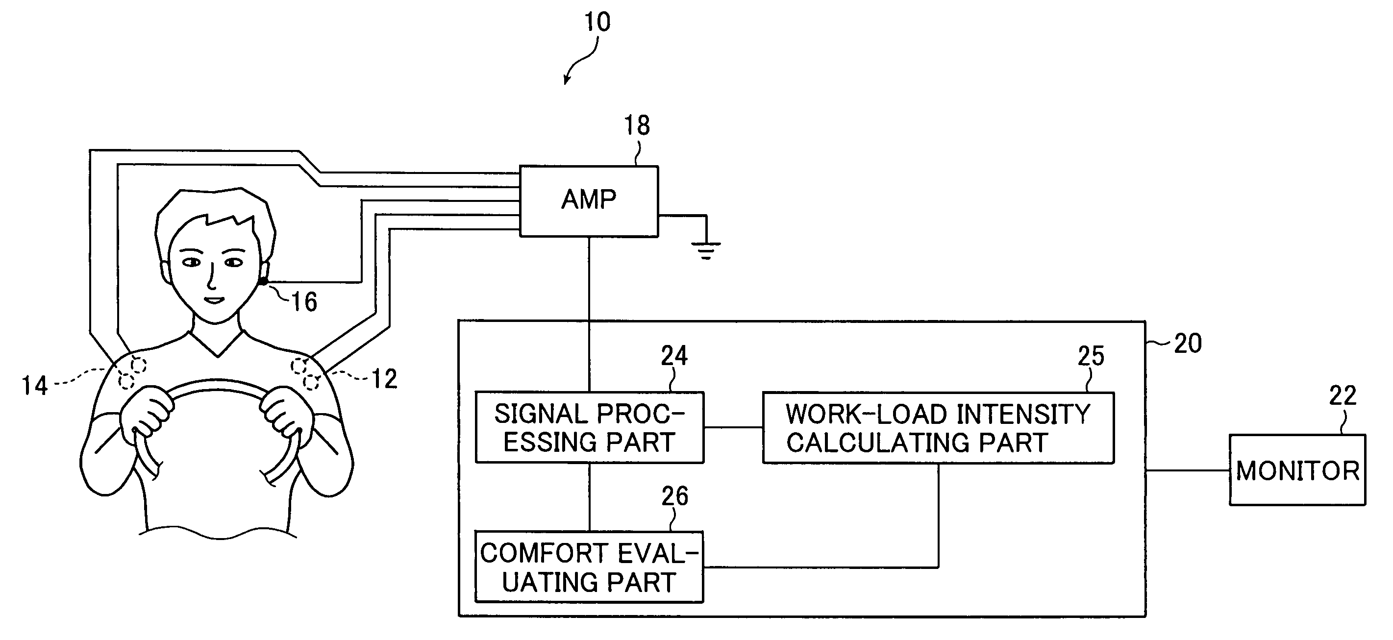
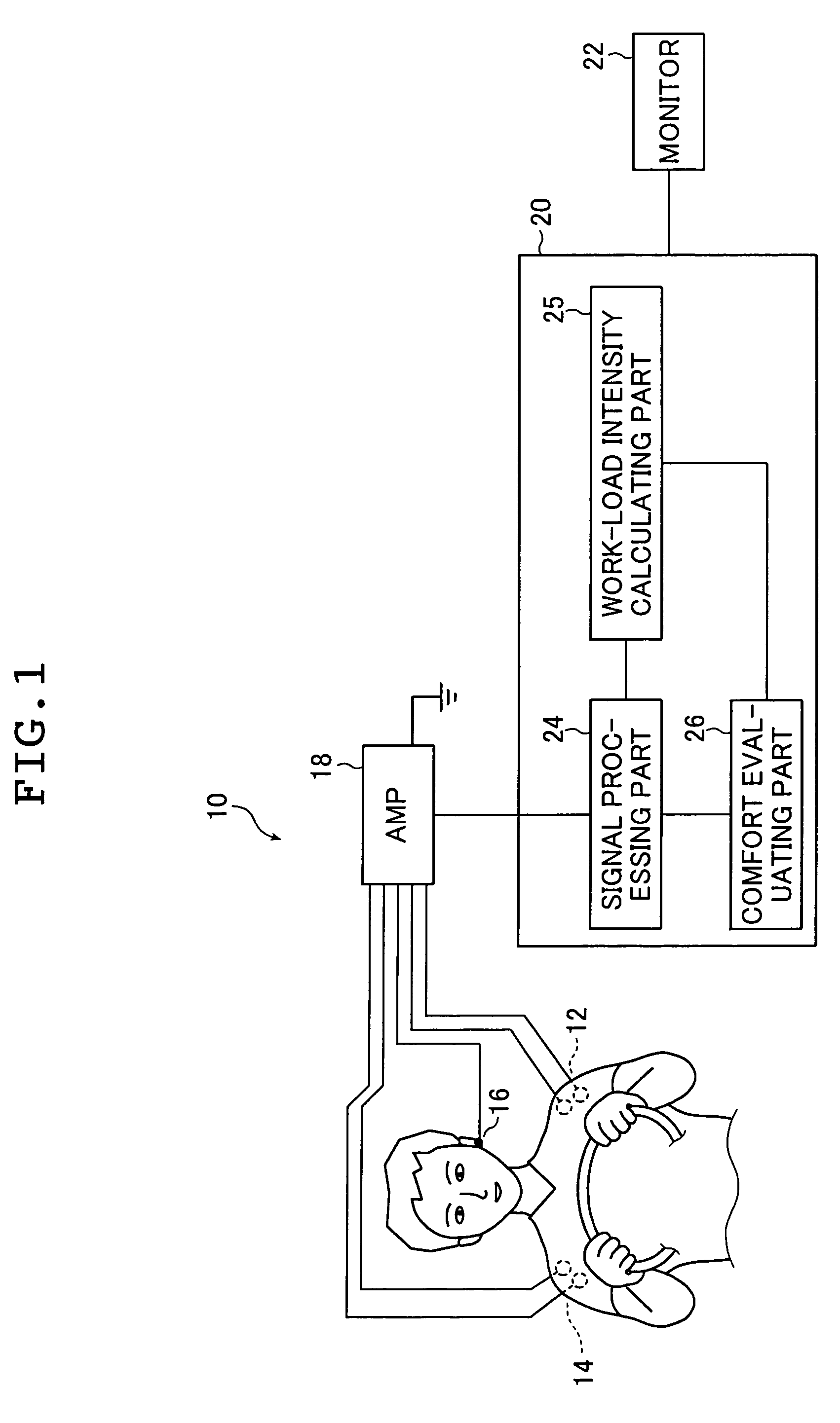
[0031]FIG. 1 is a schematic block diagram showing a steering comfort evaluating device 10 as a work comfort evaluating device of the invention applied to a driver's steering operation.

[0032]The steering comfort evaluating device 10 is a device for evaluating a level of comfort of steering operation by a driver who drives a vehicle. The steering comfort evaluating device 10 is made up of myoelectric potential detecting sensors 12 and 14 for detecting myoelectric potentials at right and left deltoid muscles of the driver, an electrode 16, an amplifier 18 for amplifying myoelectric potentials derived from the potential detecting sensors 12 and 14, a processor unit 20 for evaluating a level of steering comfort based on time-series waveforms of the amplified myoelectric potentials at the right and left deltoid muscles, and a monitor 22 for monitoring the result of the evaluation.

[0033]The myoelectric potential detecting sensor 12 is a sensor for sensing a myoelectric potential of the del...


PUM


Abstract

A work comfort evaluating device is a device for evaluating a level of comfort of work by measuring myoelectric potentials of plural muscles when the work is done by antagonistic activities of the muscles. The device has a pair of detecting sensors, an amplifier, a signal processing part, a work-load intensity calculating part, and an evaluation part. The sensors sense myoelectric potentials of the muscles at a time of the work. The signal processing part calculates a synchronous contraction intensity of the muscles by using myoelectric potential waveforms. The work-load intensity calculating part calculates a level of a work load intensity in the work. The evaluation part evaluates a level of comfort of the work by normalizing the synchronous contraction intensity by the level of the work load intensity calculated.

Description

BACKGROUND OF THE INVENTION[0001]The present invention relates to a work comfort evaluating device and method for evaluating a level of comfort of work by measuring myoelectric potentials of plural deltoid muscles when the work is done by antagonistic activities of the deltoid muscles. More particularly, the invention relates to a device and method for evaluating a steering comfort of a vehicle.[0002]At present, automobile manufacturers and tire manufacturers pursue steering easiness of a vehicle and develop vehicles and tires by using various methods in order to provide such vehicles as automobiles, and tires, which ensure comfortable steering operations. In the development of the vehicles and tires, a steering comfort is evaluated, in most cases, by using a subjective sensory evaluation of a driver, or by using a method in which physical measurement data representing a behavior of the vehicle is acquired by using a measuring sensor such as an acceleration sensor that is attached t...

Claims


Application Information

Patent Timeline
Patent Type & Authority Patents(United States)
IPC IPC(8): A61B5/04G08B23/00B62D49/06A61B5/0488A61B5/16A61B5/18A61B5/22
CPCA61B5/0488A61B5/18A61B5/228A61B5/389
Inventor KURAMORI, AKIRAKOGUCHI, NORITAKAKAMIJO, MASAYOSHISADOYAMA, TSUGUTAKE
Owner THE YOKOHAMA RUBBER CO LTD
Learn More