
Actuator for the actuation of a clutch and/or a gear mechanism

a technology of gear mechanism and clutch, which is applied in the direction of clutches, emergency protective circuit arrangements, mechanical equipment, etc., can solve the problems of motor vehicles being brought into uncritical operating state, limited in the extent of electric motor positioning, etc., and achieves the effect of reducing circuit technology complexity

Inactive Publication Date: 2009-02-03
LUK LAMELLEN & KUPPLUNGSBAU BETEILIGUNGS KG
View PDF9 Cites 0 Cited by
  • Summary
  • Abstract
  • Description
  • Claims
  • Application Information

AI Technical Summary

Benefits of technology

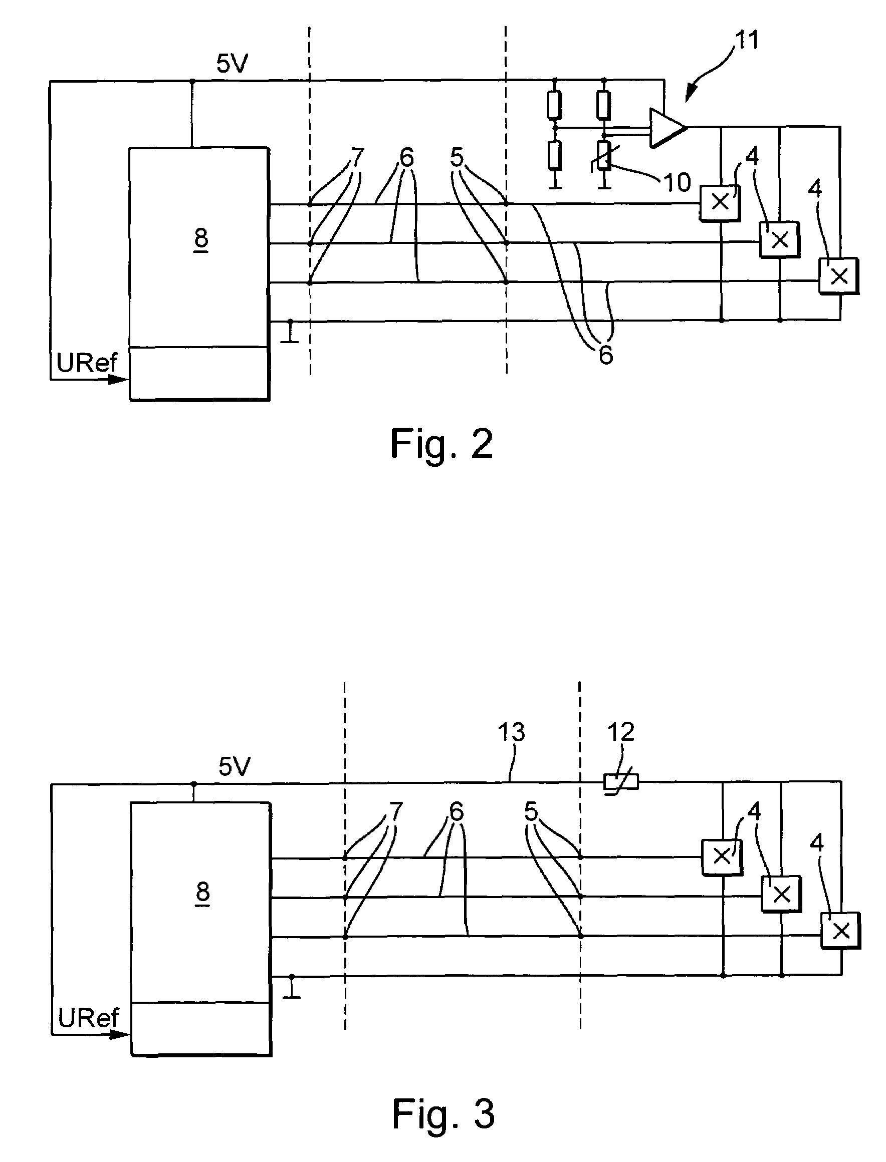
[0006]It is advantageous if the temperature-monitoring device is in controlling connection with the power supply device in such a manner that on the occurrence of an operating temperature lying outside of the range of theoretical values the electrical power supply voltages present at the operating voltage connections of all of the Hall sensors is reduced or switched off. The temperature-limiting device for the electric motor can then be produced still more economically.
[0009]Thereby, the temperature warning and switch-off function for the electric motor can be realized economically with very little complexity in circuit technology.
[0010]On overshoot of a predefined operating temperature of the electric motor a measurement error in the position measurement signal is simulated in order to achieve a switch-off and / or a limiting of power of the electric motor. The request for the switch-off and / or the power limit can thus be accomplished in a simple manner via the lines already present for the transmission of the position measurement signal.
[0012]One object of the invention is to provide an actuator of the type stated in the introduction which can be produced economically and makes possible compact dimensions. Furthermore, there is the objective of specifying a process of the type stated in the introduction which can be carried out economically.
[0014]Thereby, the lines provided for the transmission of the position measurement signal between the incremental encoder and the control device can also be used in an advantageous manner to disconnect and / or to limit the power supply of the electric motor if an operating state should ever occur in which the operating temperature of the electric motor exceeds a predefined limit value. In this way, an additional control line between the incremental encoder and the control device can be spared. The components present for a traditional actuator without a temperature-monitoring device, such as, for example, the control device, electrical connecting cables, or cable connector plugs, can be carried over without change to the actuator according to the invention. Since the operating temperature of the electric motor under unfavorable conditions of operation is limited, the electric motor can be dimensioned smaller than would be possible without such a limit. With this, one accepts in the bargain a limit of power and / or a switching off of the electric motor, and a reduction in convenience possibly associated therewith, under conditions of operation leading to a thermal peak load of the electric motor and occurring only very rarely in practice.

Problems solved by technology

On the occurrence of a temperature warning the electric motor can initially continue to be controlled via the control device, where, however, the control is accomplished in such a manner that positioning movements of the electric motor are limited to a necessary extent.
Before switching off the electric motor, the motor vehicle can, if necessary, be brought into an uncritical operating state.

Method used


Image

  • Actuator for the actuation of a clutch and/or a gear mechanism
  • Actuator for the actuation of a clutch and/or a gear mechanism
  • Actuator for the actuation of a clutch and/or a gear mechanism

Examples


Embodiment Construction

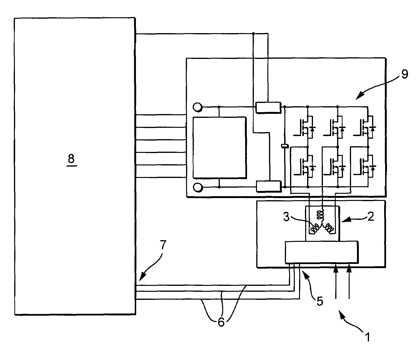
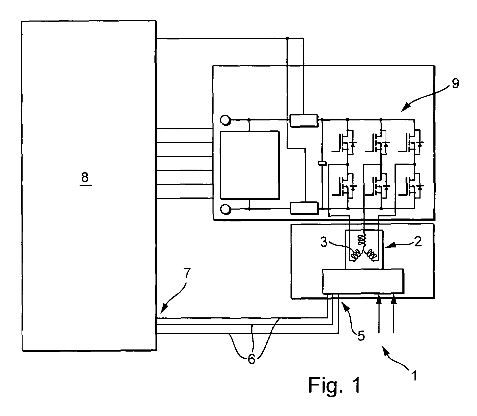
[0025]As seen in FIG. 1, actuator 1 for a motor vehicle comprises an electric motor 2 which is connected, via a gear mechanism not represented in more detail in the drawing, to an actuating element for a plate clutch. The electric motor 2 comprises a primary part with a motor winding 3 and a permanent-magnet secondary part. At the periphery of the secondary part a row of magnetic segments is disposed, in a manner known per se, which has alternating north and south poles and works together with the winding via an air gap.

[0026]An incremental encoder, which comprises several Hall sensors 4 which are disposed so as to be fixed on the primary part, which are spaced from one another in the peripheral direction of the primary part, and which face the secondary part's magnetic segments and detect their magnetic field, is provided on the electric motor 2 to register the position of the secondary part relative to the primary part.

[0027]The incremental encoder comprises a position measurement...


PUM


Abstract

An actuator for a clutch or gear mechanism in a motor vehicle comprises an electric motor and an incremental encoder. The encoder comprises a position measurement signal output at which a position measurement signal can be output which has a number of different signal states, each of which is assigned to a relative position between a primary part and a secondary part of the electric motor. For the commutation of the electric motor, the position measurement signal output is connected to a position measurement signal input of a control device for a motor winding of the electric motor. The control device comprises a device for checking the plausibility of the position measurement signal and is designed in such a manner that on the occurrence of an implausible signal state the power supply to the electric motor is disconnected and / or the power of the electric motor is limited.

Description

CROSS REFERENCE TO RELATED APPLICATIONS[0001]This patent application claims priority of German Patent Application No. 10 2005 060 599.0, filed Dec. 17, 2005, which application is incorporated herein by reference.FIELD OF THE INVENTION[0002]The invention relates to an actuator for actuation of a clutch and / or a gear mechanism in a motor vehicle, comprising an electric motor and an incremental encoder therefor, where the incremental encoder comprises a position measurement signal output at which it is possible to output a position measurement signal having a number of different signal states, each of which is assigned to a relative position between a primary part and a secondary part of the electric motor, where, for the commutation of the electric motor, the position measurement signal output is connected to a position measurement signal input of a control device for a motor winding of the electric motor, where the control device comprises a device for checking the plausibility of th...

Claims


Application Information

Patent Timeline
Patent Type & Authority Patents(United States)
IPC IPC(8): H02H5/04
CPCF16D48/064F16H59/72F16H61/12F16H61/32F16D2500/1025F16D2500/3021F16D2500/3026F16D2500/501F16D2500/5108F16D2500/5114F16D2500/70418F16D2500/7101F16H2061/1208
Inventor PFUND, THOMASBUCHET, WAI-WALKRO, SVEN-JOSTEINZIMMERMANN, MARTINGERHART, JUERGENFUSS, MARTIN
Owner LUK LAMELLEN & KUPPLUNGSBAU BETEILIGUNGS KG
Learn More