
Manhole cover security lock with controlled pressure release

a manhole cover and control technology, applied in the field of manhole covers, can solve the problems of significant maintenance cost, high pressure on the manhole cover seat, and high pressure on the manhole cover, and achieve the effect of reducing the magnitude of the peak pressur

Active Publication Date: 2009-02-03
NEENAH FOUNDRY
View PDF19 Cites 39 Cited by
  • Summary
  • Abstract
  • Description
  • Claims
  • Application Information

AI Technical Summary

Benefits of technology

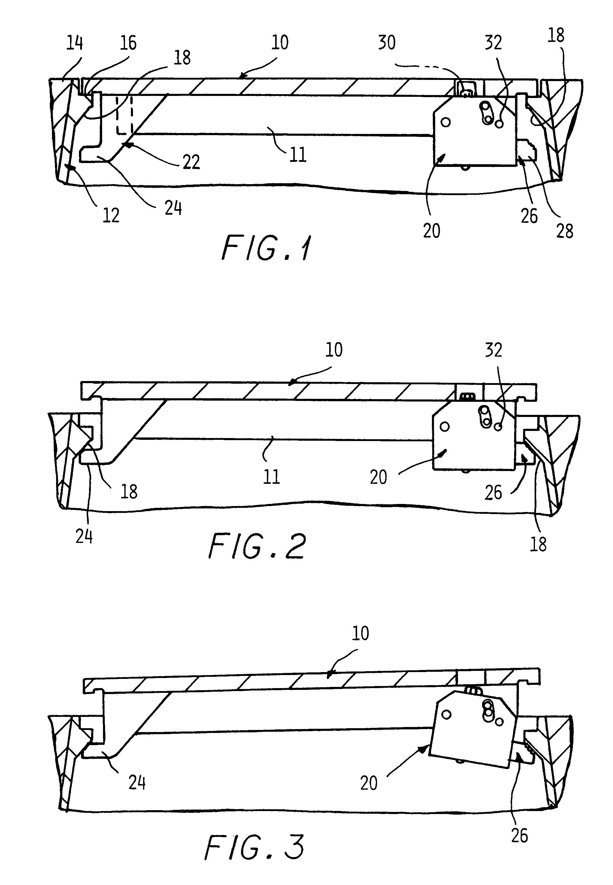
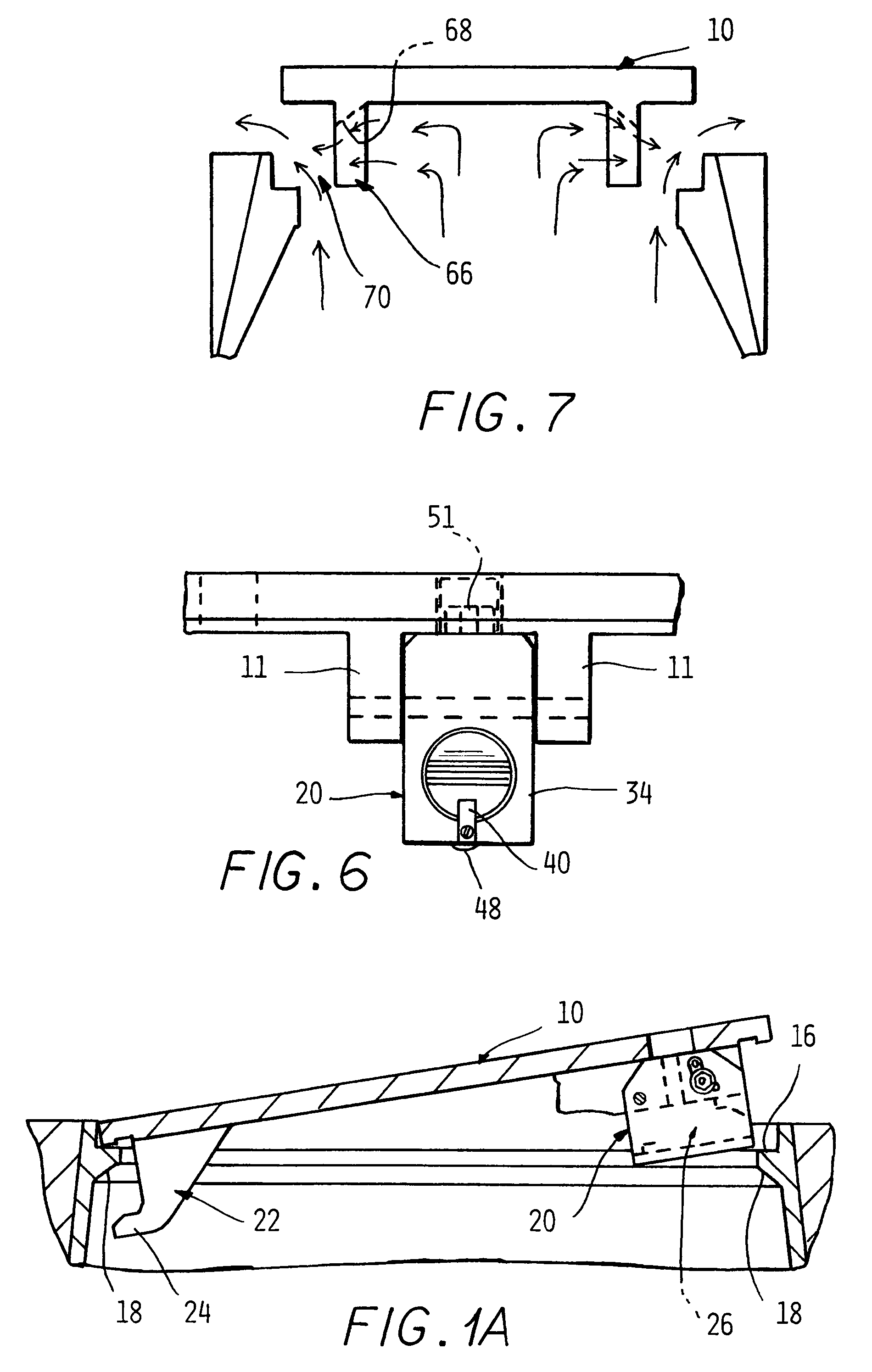
"The present invention relates to a lock body for a manhole cover that can withstand high pressures during an explosion without allowing the cover to be blown free. The lock body is mounted on the manhole cover and can pivot upward to create a gap between the cover and the manhole, allowing gas to vent while preventing the cover from being blown free. The lock body has a stop that prevents it from pivoting downward beyond a certain force level, allowing the cover to rise a predetermined short increment higher to create a greater venting area for the exit of explosive gases. The manhole cover also has scalloped slots shaped to redirect the exiting gases back toward the clearance gap around the cover, reducing the magnitude of the peak pressure developed beneath the cover from that which would otherwise develop."

Problems solved by technology

However, manhole covers are sometimes subjected to very high pressures caused by explosions as when an accumulation of methane gas, etc. in the passages below is ignited.
Manhole vault explosions usually blow the manhole covers out of their seats and into the air with great force.
Since each manhole cover must be reinstalled as soon as possible after an explosion to cover up the hazardous open manhole, a significant maintenance cost is entailed.
Until a dislodged manhole cover can be replaced into its frame, the open manhole presents a serious hazard.
Although such explosive events are rare, when they do occur, manhole covers are often blown high into the air, can cause much damage, and even become deadly if a manhole cover strikes a passerby.
Fixing manhole covers in place on their seats could cause damage to enclosing structures if there is no venting of the rapidly expanding gases.

Method used


Image

  • Manhole cover security lock with controlled pressure release
  • Manhole cover security lock with controlled pressure release
  • Manhole cover security lock with controlled pressure release

Examples


Embodiment Construction

[0033]In the following detailed description, certain specific terminology will be employed for the sake of clarity and a particular embodiment described in accordance with the requirements of 35 USC 112, but it is to be understood that the same is not intended to be limiting and should not be so construed inasmuch as the invention is capable of taking many forms and variations within the scope of the appended claims.

[0034]Referring to the drawings, FIG. 1 shows a manhole cover 10 resting on a seat 16 defined by a metal enclosure 12 recessed into street paving 14 and defining the manhole cavity itself. The enclosure 12 has an inwardly sloping annular feature 18 having the seat 16 defined on the top surface.

[0035]According to the present invention, a security locking arrangement is provided, comprised of a lock body assembly 20 fixed to the underside of the manhole cover 10 adjacent to the outer perimeter thereof in the space between two parallel extending ribs 11 extending across the...


PUM


Abstract

A controllably releasable security locking arrangement for a manhole cover allows a manhole cover to be locked into position but allows the manhole cover to rise up in stages upon development of upward forces in an explosion to vent gases developed by the explosion. A lock body mounts a latch slide which has an outer end and which can be extended to prevent removal of the manhole cover. When a shear pin fails the lock body pivots down, to a limited extent, and a secondary shear pin can also be included allowing the cover to be blown completely free upon development of pressures of a great magnitude. A slotted skirt directs venting gas flow so as to retard the inflow of free air and attenuate the explosion.

Description

CROSS REFERENCE TO RELATED APPLICATIONS[0001]This application claims the benefit of U.S. provisional patent applications No. 60 / 921,975 filed on Apr. 6, 2007; No. 60 / 889,553 filed on Feb. 13, 2007; and No. 60 / 812,757 filed on Jun. 12, 2006.BACKGROUND OF THE INVENTION[0002]This invention concerns manhole covers used to close off access to utility passages extending beneath city streets. For security purposes, it is desirable to limit access to such passages by locking the manhole covers onto their supporting seats.[0003]However, manhole covers are sometimes subjected to very high pressures caused by explosions as when an accumulation of methane gas, etc. in the passages below is ignited.[0004]Manhole vault explosions usually blow the manhole covers out of their seats and into the air with great force. Since each manhole cover must be reinstalled as soon as possible after an explosion to cover up the hazardous open manhole, a significant maintenance cost is entailed.[0005]Until a disl...

Claims


Application Information

Patent Timeline
Patent Type & Authority Patents(United States)
IPC IPC(8): E02D29/14
CPCE02D29/1418E02D29/1463E02D29/1427
Inventor STADLER, DAVID
Owner NEENAH FOUNDRY
Learn More