
Deformable structure and cable support system

a technology of deformation structure and support system, which is applied in the direction of cable arrangement between relatively moving parts, coupling device connections, manufacturing tools, etc., can solve the problems of excessive tightening of cable to be broken, excessive slackening of cable, and inability to meet the needs of cable support system including the support ring, etc., to achieve prevent breakage, simple construction, and high strength

Active Publication Date: 2009-02-03
KAWASAKI HEAVY IND LTD
View PDF14 Cites 38 Cited by
  • Summary
  • Abstract
  • Description
  • Claims
  • Application Information

AI Technical Summary

Benefits of technology

The present invention provides a cable support system with a deformable structure that can maintain a predetermined shape without additional support members. The deformable structure includes a plurality of connecting parts that are arranged in a longitudinal axis and connected to each other so that each connecting part can turn relative to the others. The deformable structure can be extended along a circular arc of a predetermined allowable radius of curvature by inclining the first axes of the connecting parts at a fixed angle. The deformable structure is designed to have high strength and can support a flexible cable near the outer surface of a driving apparatus. The cable support system includes a deformable structure and a base structure that can be easily attached to the cable support system. The base structure has stopping parts that come into contact with the connecting parts to prevent excessive deformation of the deformable structure. The cable support system can maintain a desired deformed shape without using additional support members.

Problems solved by technology

In some cases the cable is excessively slackened to collide against the peripheral device, or the cable is excessively tightened to be broken, if the shafts of the robot are displaced greatly
The cable support system including the support ring is inevitably large.
If the axis of rotation is horizontal, the deformable structure is unable to maintain a predetermined position and is unable to support a cable.
The structural strength of the joint is low and the joint is subject to breakage.
Therefore, the deformable structure cannot be formed in a large weight.
The same problem arises when the axis of rotation is horizontal, a heavy cable is supported by the deformable structure, or a high acceleration is imparted to the deformable structure.

Method used


Image

  • Deformable structure and cable support system
  • Deformable structure and cable support system
  • Deformable structure and cable support system

Examples


Embodiment Construction

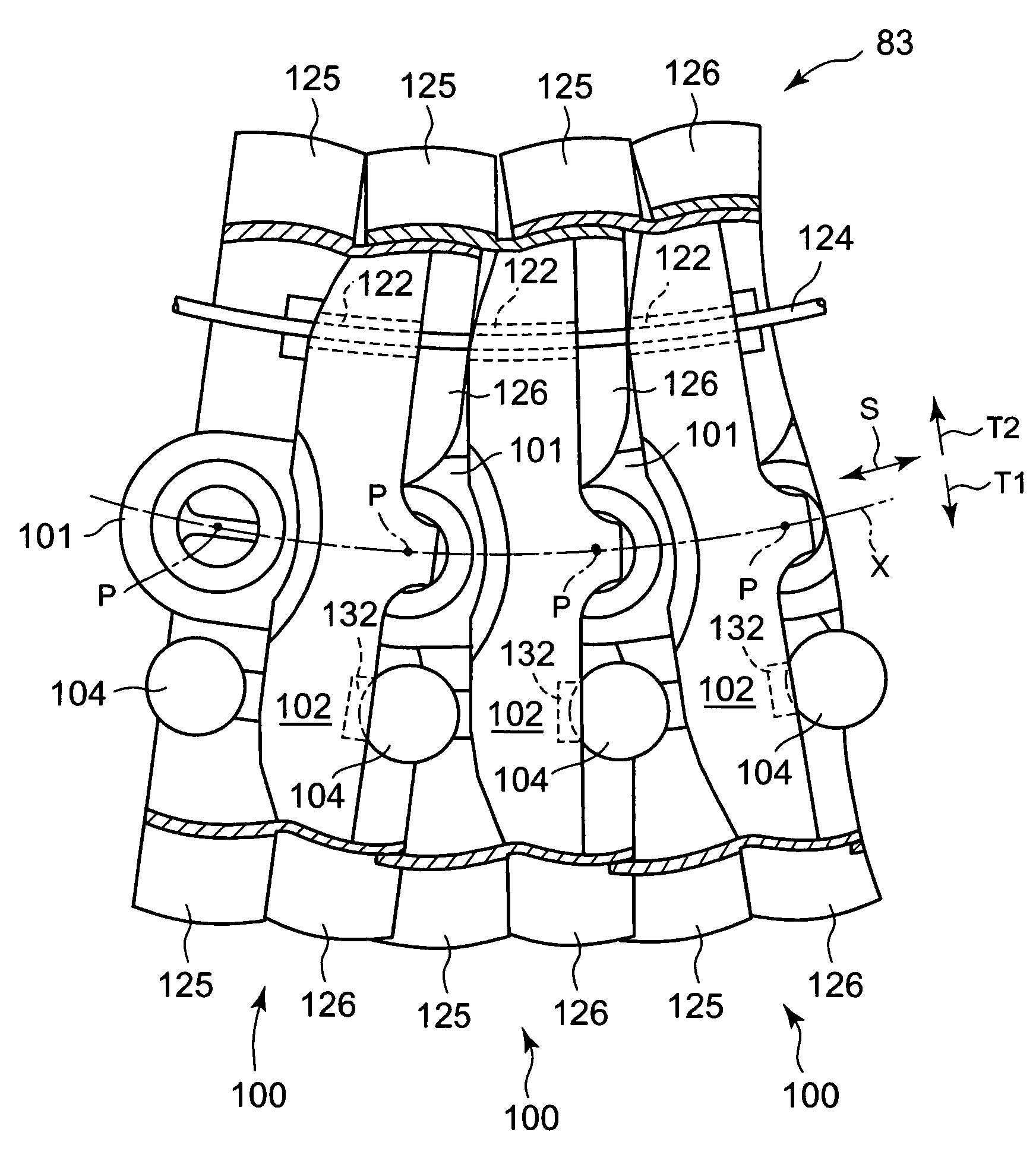
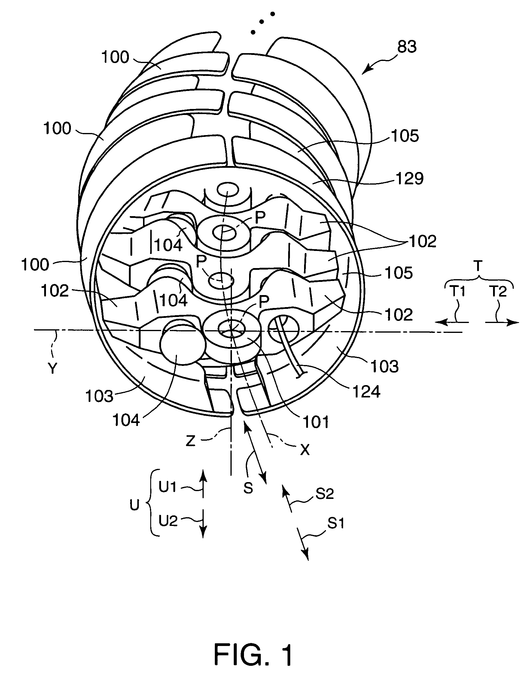
[0062]As shown in FIG. 1, the deformable structure 83 is an elongate structure of a shape substantially resembling a circular arc. The deformable structure 83 can be deformed in a predetermined deforming direction by a predetermined amount of deformation and cannot be deformed in a predetermined undeformable direction. The deformable structure 83 is an integral component of a cable support system, which will be described later. The cable support system supports a cable so as to extend around a driving apparatus of a robot or the like.

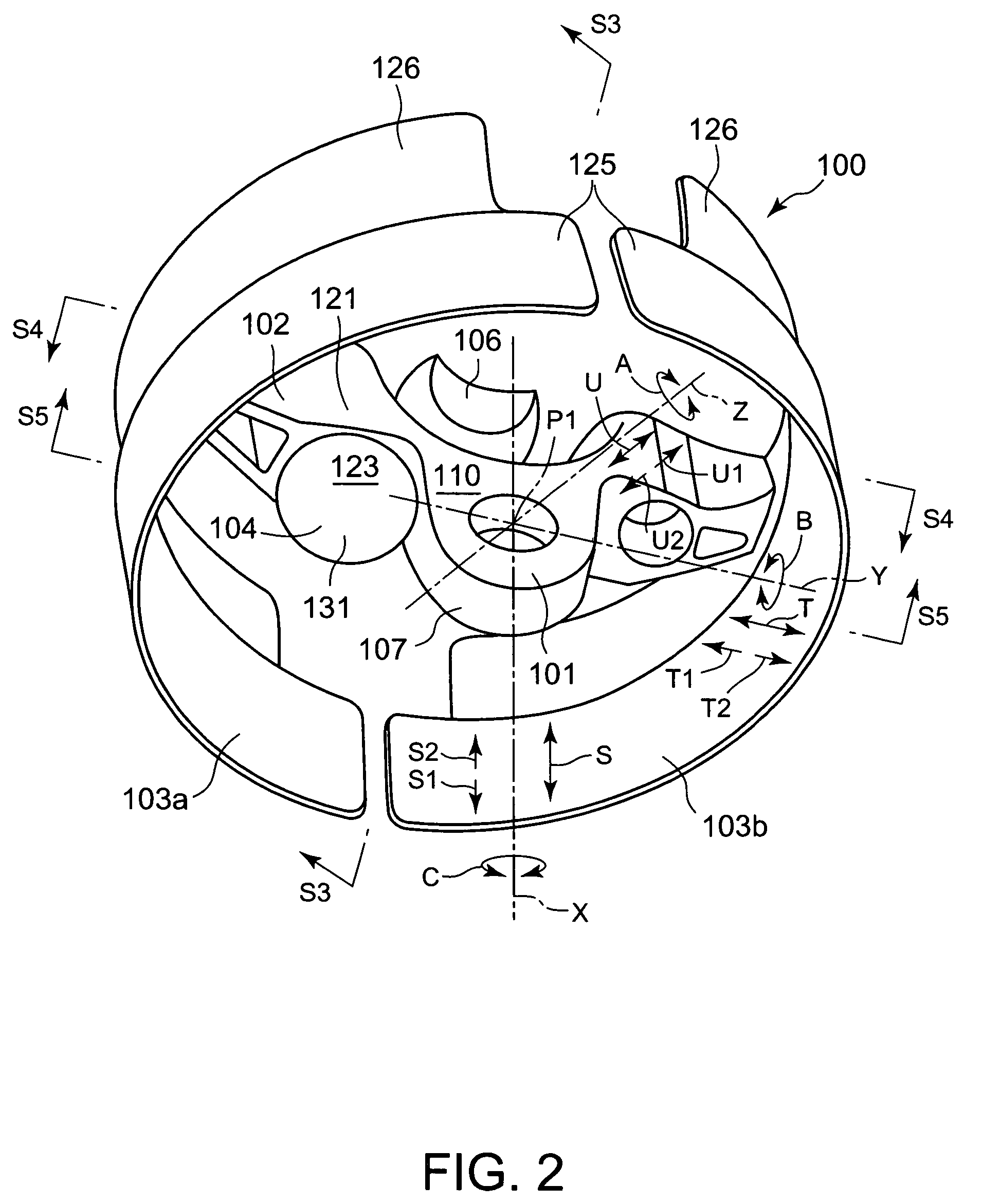
[0063]The deformable structure 83 is formed in the shape of a circular arc having a predetermined radius of curvature. The deformable structure 83 has a plurality of turnable segments 100 arranged in a direction S parallel to a longitudinal axis X. The turnable segments 100 are arranged at equal intervals in a longitudinal direction S and the adjacent turnable segments 100 are connected with each other. One of the two adjacent turnable segments 100 can ...


PUM


Abstract

In a deformable structure, connecting parts each of which has a base part are arranged longitudinally so that adjacent connecting parts are connected to each other. Respective first axes of the adjacent connecting parts are inclined to each other in a state that a spacer on one of the two adjacent base parts comes into contact with the other base part. When an external force is exerted on the deformable structure, the spacers restrain the deformable structure from being further curved into a radius of curvature smaller than a predetermined allowable radius of curvature. Most of the external force exerted on the deformable structure is born by the base parts and the spacers so that only a low force acts on the connecting parts. Thus the connecting parts do not break easily so that the deformable structure has a high strength.

Description

CROSS REFERENCE TO RELATED APPLICATIONS[0001]This application is based upon the prior Japanese Patent Application No. 2005-125723 filed on Apr. 22, 2005, the entire contents of which are incorporated herein by reference.BACKGROUND OF THE INVENTION[0002]1. Field of the Invention[0003]The present invention relates to a deformable structure employed in a cable support system for supporting a flexible cable. More particularly, the present invention relates to a deformable structure employed in a cable support system for supporting a cable on an industrial robot.[0004]2. Description of the Related Art[0005]A cable is extended along the outer surface of robot arms in an industrial robot (hereinafter referred to simply as “robot”). The cable has one end connected to an end effector and the other end connected to a peripheral device, such as a power unit. The cable includes bundles of wires for carrying power to the end effector and those for carrying command signals to the end effector and...

Claims


Application Information

Patent Timeline
Patent Type & Authority Patents(United States)
IPC IPC(8): F16G13/16H02G11/00
CPCB25J19/0025F16L3/015F16L3/26F16L57/02H02G11/00F16G13/16
Inventor HARADA, TAKASHIMAEGUCHI, YUJIINADA, TAKAHIRO
Owner KAWASAKI HEAVY IND LTD
Learn More