Eureka AIR delivers breakthrough ideas for toughest innovation challenges, trusted by R&D personnel around the world.

Vertebral fixing system

a technology of fixing system and vertebrae, which is applied in the field of vertebral fixing system, can solve the problems of paralysis of patients, small cases or deterioration, and difficulty in using such hooks, and achieve the effect of preventing relative displacemen

Inactive Publication Date: 2009-01-27
ZIMMER SPINE SAS
View PDF13 Cites 195 Cited by
  • Summary
  • Abstract
  • Description
  • Claims
  • Application Information

AI Technical Summary

Benefits of technology

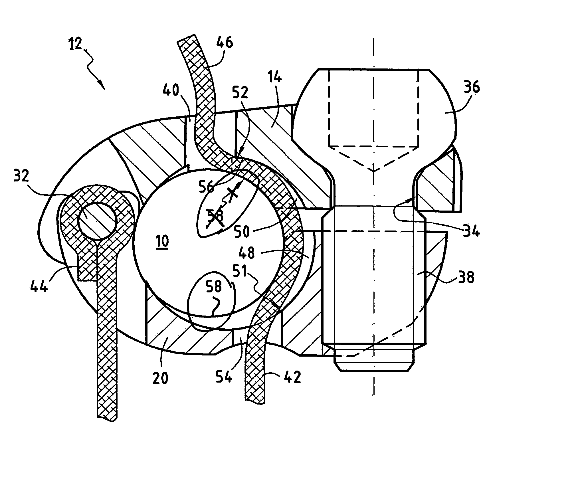
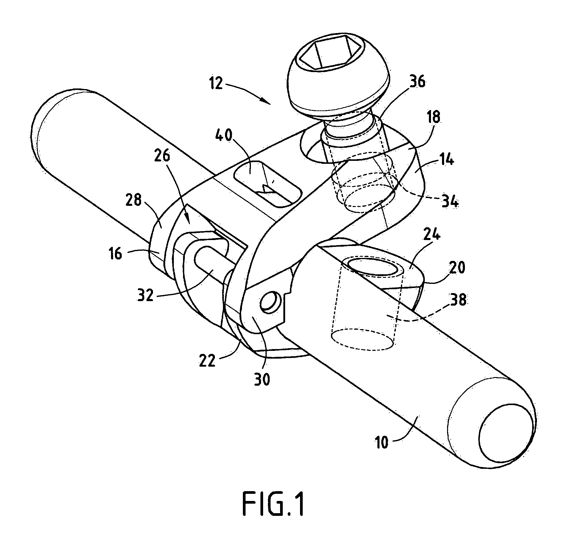
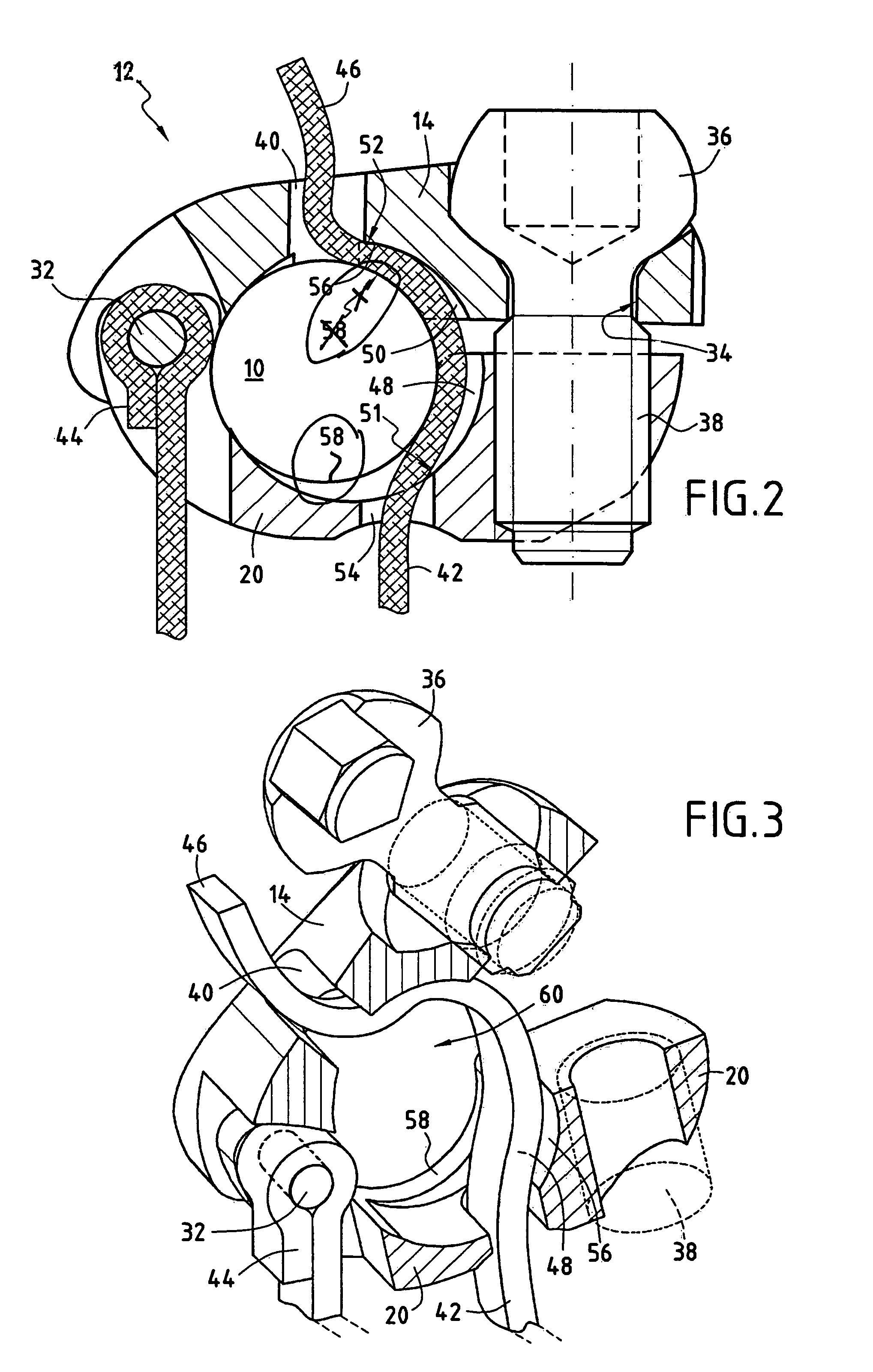
[0011]To achieve the above object, a first aspect of the present invention proposes a vertebral fixing system that comprises: a connecting part adapted to face said rib and / or said transverse process and to be connected to said rod, an elongate flexible ligature adapted to connect together said connecting part and at least one rib and / or one transverse process, and adjustable locking means fastened to said connecting part and adapted to fix simultaneously in position said connecting part relative to said rod and at least one portion of said ligature relative to said connecting part, so as to prevent relative displacement of said rod and said vertebra in opposite directions.
[0012]Thus one feature of the invention resides in the method of connecting said rod with said vertebrae using the connecting part that connects together the flexible ligature and said rod. The ligature, one end of which is connected to said rib and / or transverse process, is adapted to be immobilized in said connecting part by the adjustable locking means, which also fix said connecting part in position relative to said rod, with the result that relative displacement of said rod and said vertebra is prevented, at least in the opposite direction.
[0019]It is particularly advantageous if said second ends of the two longitudinal members have, facing each other, a bore in one and a thread in the other, so that a screw may be passed through said bore and screwed into said thread and form said adjustable locking means.
[0023]It is particularly advantageous if said passage extends between two orifices in said connecting part and opening to the outside of said part so that said ligature is able to slide through said part.
[0024]Said ligature is therefore perfectly guided inside said connecting part in said passage with the result that stretching of the free second end of said ligature cannot divert said ligature from said passage, regardless of the driving angle relative to said connecting part. During the stretching of said free send end of said ligature, the adjustable locking means immobilize at least a portion of said ligature.
[0027]Thus, according to this feature, the pressure of said ligature on the rod may be controlled by the adjustable locking means so that the free second end of said ligature may be forcibly stretched, to tension it. Once it has been tensioned, the adjustable locking means may be operated to immobilize the ligature completely relative to the rod and to immobilize the connecting part relative to the rod. The loop formed around the rib and / or the transverse process by said ligature is therefore of fixed size and maintains the tension in said connecting part facing the posterior wall of said vertebra.

Problems solved by technology

However, using such hooks is difficult because the operative must not under any circumstances touch the spinal cord that extends along the centre of the spinal canal, since that would result in paralysis of the patient.
However, they must be inserted into the pedicles of the vertebrae, which in some cases are small or have deteriorated.

Method used


Image

  • Vertebral fixing system
  • Vertebral fixing system
  • Vertebral fixing system

Examples


Embodiment Construction

[0033]FIG. 1 shows a vertebral fixing system of the invention mounted on a rod 10. The vertebral fixing system comprises a connecting part 12 having two longitudinal members, of which a first longitudinal member 14 extends between a first end 16 and a second end 18 and a second longitudinal member 20 extends between a first end 22 and a second end 24. The two longitudinal members 14 and 20 are pivoted together at their first ends 16 and 22 for the purposes of mounting the system. The first end 16 of the longitudinal member 14 has a notch 26 with two opposite edges 28 and 30 and between which the first end 22 of the other longitudinal member 20 may be inserted. A pivot pin 32 passes through the two first ends 16 and 22 and is free to rotate in at least one of said ends 16 and / or 22. The second end 18 of the first longitudinal member 14 includes a bore 34 into which a screw 36 may be inserted. The second end 24 of the second longitudinal member 20 comprises a thread 38 which is aligne...


PUM


Abstract

The present invention relates to a vertebral fixing system adapted to be mounted on a vertebra of the spine to connect it to a rod. The fixing system comprises: a connecting part adapted to face the rib and / or the transverse process and to be connected to the rod; an elongate flexible ligature adapted to connect together the connecting part and at least one rib and / or one transverse process; and an adjustable locking screw fastened to the connecting part and adapted to fix simultaneously in position the connecting part relative to the rod and at least one portion of the ligature relative to the connecting part, so as to prevent relative displacement of the rod and the vertebra in opposite directions.

Description

BACKGROUND OF THE INVENTION[0001]1. Field of the invention[0002]The present invention relates to a vertebral fixing system adapted to be mounted on a vertebra, and to a spine-straightening assembly using the system.[0003]One field of application that is envisaged, is particularly but not exclusively, the treatment of scoliosis or, more generally, the correction of abnormal curvatures of the spine.[0004]2. Description of the Related Art[0005]The spine is formed of superposed vertebrae, normally aligned along a vertebral axis, from the lumbar vertebrae to the cervical vertebrae, and each having a posterior wall from which projects a spinous process and two lateral edges from the walls of which there project ribs and / or transverse processes. If the spine of a person has abnormal curvature, the vertebrae are inclined relative to each other and relative to said vertebral axis. The lateral edges of the vertebrae on one side are therefore closer together and form a concave shape while the ...

Claims


Application Information

Patent Timeline
IPC IPC(8): A61B17/70A61B17/56A61B17/84
CPCA61B17/7053A61B17/707A61B17/7041A61B17/70
Inventor MAZDA, KEYVANLE COUEDIC, REGIS
Owner ZIMMER SPINE SAS
Why Eureka
Eureka Blog
Learn More