Side-pumped solid-state laser source, and pumping process for a solid-state laser source

a laser source and laser technology, applied in laser cooling arrangements, laser details, optical resonator shape and construction, etc., can solve the problems of difficult to optimise power extraction and control the spatial quality of the generated laser beam, and negatively influence the thermal focal length generated within the crystal, so as to facilitate the symmetization of the thermal focal length seen by the oscillating mod

Active Publication Date: 2009-01-20
LASERVALL
View PDF6 Cites 0 Cited by
  • Summary
  • Abstract
  • Description
  • Claims
  • Application Information

AI Technical Summary

Benefits of technology

[0015]Another object of the invention is to provide a laser source which is optimised, compact and economical.

Problems solved by technology

The most common problems linked to a side-pumping geometry of this type relate to the distribution of the pumping beam within the crystal, which is dishomogeneous and negatively influences the thermal focal length generated within the crystal.
Another problem is the poor optimisation of the spatial superposing (matching) between the pumping beam and the fundamental oscillating mode within the cavity, which negatively influences the spatial quality of the generated laser beam.
In a system of this type it is extremely difficult to optimise power extraction and to control the spatial quality of the generated laser beam.

Method used


Image

  • Side-pumped solid-state laser source, and pumping process for a solid-state laser source
  • Side-pumped solid-state laser source, and pumping process for a solid-state laser source
  • Side-pumped solid-state laser source, and pumping process for a solid-state laser source

Examples


Embodiment Construction

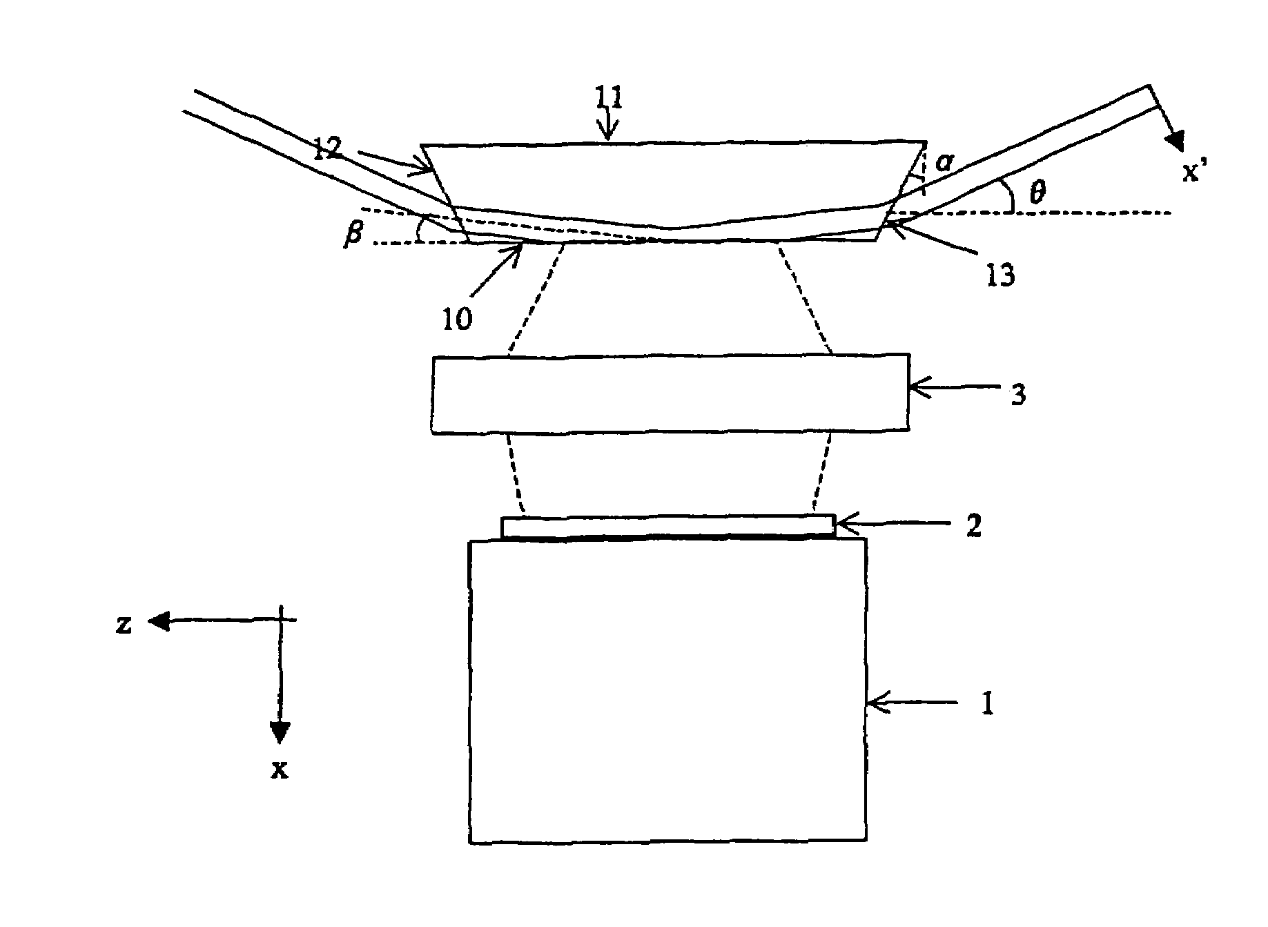
[0030]With reference to said figures, these show a side-pumped solid-state laser source for industrial applications, indicated overall by the reference numeral 20.

[0031]The laser source 20 comprises a resonant cavity 21 defined by at least two spaced-apart mirrors 22, 23, an active medium of laser crystal type 24 positioned in the resonant cavity, means 25 for actively controlling the temperature of the laser crystal 24, and a Q-switch 26 positioned in the resonant cavity 21 between the laser crystal 24 and one of the two mirrors (the mirror 22 in the illustrated embodiment).

[0032]The laser source 20 also comprises a laser diode pumping source.

[0033]The cavity layout (this expression meaning the crystal together with the mirrors defining the cavity) and the lenses for conditioning the pumping beam are arranged to cause spatial inversion of the oscillating mode within the active medium in the absorption direction of the pumping beam, such as to symmetrize the thermal focal length see...


PUM


Abstract

The side-pumped solid-state laser source comprises a resonant cavity defined by at least two spaced-apart mirrors, an active medium of laser crystal type placed in said resonant cavity, and a pumping source, the layout of the resonant cavity, defined by the crystal and by the mirrors, being arranged to cause spatial inversion of the oscillating mode within the active medium in the absorption direction of the pumping beam, such as to symmetrize the thermal focal length seen by the oscillating mode. The laser source comprises lenses for conditioning the pumping beam emitted by the pumping source, to form on the side face of the laser crystal a pumping spot arranged to symmetrize the spatial quality of the emitted laser beam and / or active control means for the laser crystal temperature, in order to correct its undesired astigmatic effects. The pumping process for the solid-state laser source generates on the side face of the laser crystal a pumping spot arranged to symmetrize the spatial quality of the emitted laser beam, in such a manner as to correct its undesired astigmatism effects.

Description

FIELD OF THE INVENTION[0001]The present invention relates to a side-pumped solid-state laser source for industrial applications and a pumping process for a solid-state laser source.BACKGROUND OF THE INVENTION[0002]In particular, the invention relates to a solid-state laser source of neodymium-host type, comprising an active medium side-pumped by a laser diode and lenses for conditioning the pumping beam using a cavity layout for which the oscillating mode undergoes total reflection within the active crystal on the face struck by the pumping beam.[0003]With the proposed layout and without the need to use cavity lenses, undesirable astigmatism effects can be corrected typical of a source using a side pumping system, and the spatial quality of the generated beam can be carefully controlled.DISCUSSION OF THE RELATED ART[0004]Traditionally, a solid-state laser source with a diode side-pumping system consists of a crystal (as active medium) of circular section (rod) or rectangular section...

Claims


Application Information

Patent Timeline
Patent Type & Authority Patents(United States)
IPC IPC(8): H01S3/04H01S3/08H01S3/093
CPCH01S3/0941H01S3/042H01S3/0606H01S3/0625H01S3/08072H01S3/0815H01S3/1028H01S3/117
Inventor ZANZOLA, PAOLA
Owner LASERVALL
Why Eureka
Try Eureka