
Prismatic battery having electrolyte injection-hole capable of excellent sealing-disposition

a technology of electrolyte injection and electrolyte, which is applied in the field of high-sealed electrolyte injection holes of batteries, can solve the problems of low lowered sealability and badly affecting the sealing of electrolyte injection holes. achieve the effect of high electrolyte sealability

Active Publication Date: 2009-01-20
LG ENERGY SOLUTION LTD
View PDF7 Cites 4 Cited by
  • Summary
  • Abstract
  • Description
  • Claims
  • Application Information

AI Technical Summary

Benefits of technology

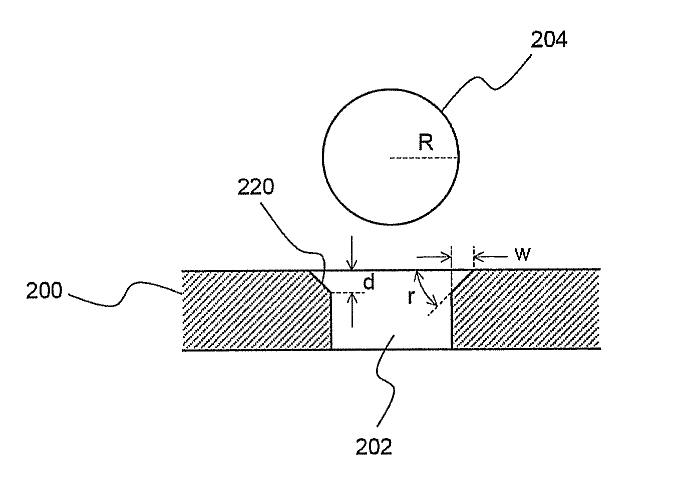
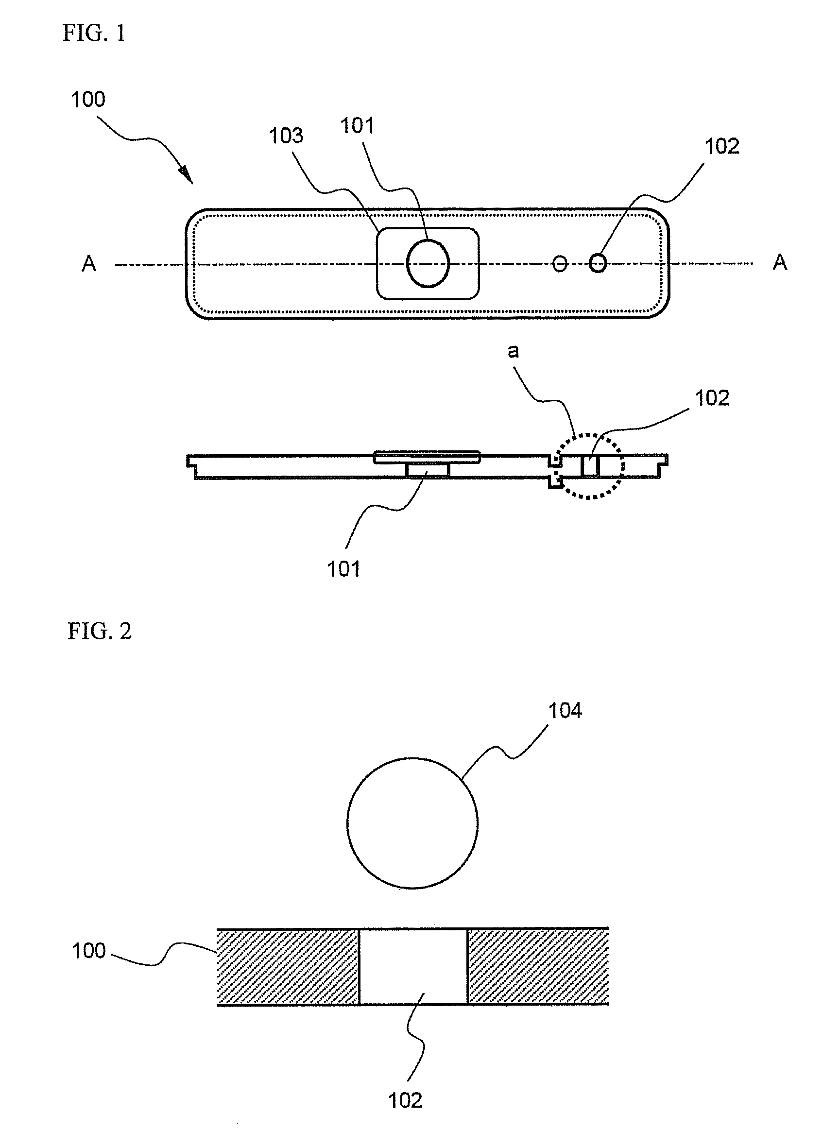
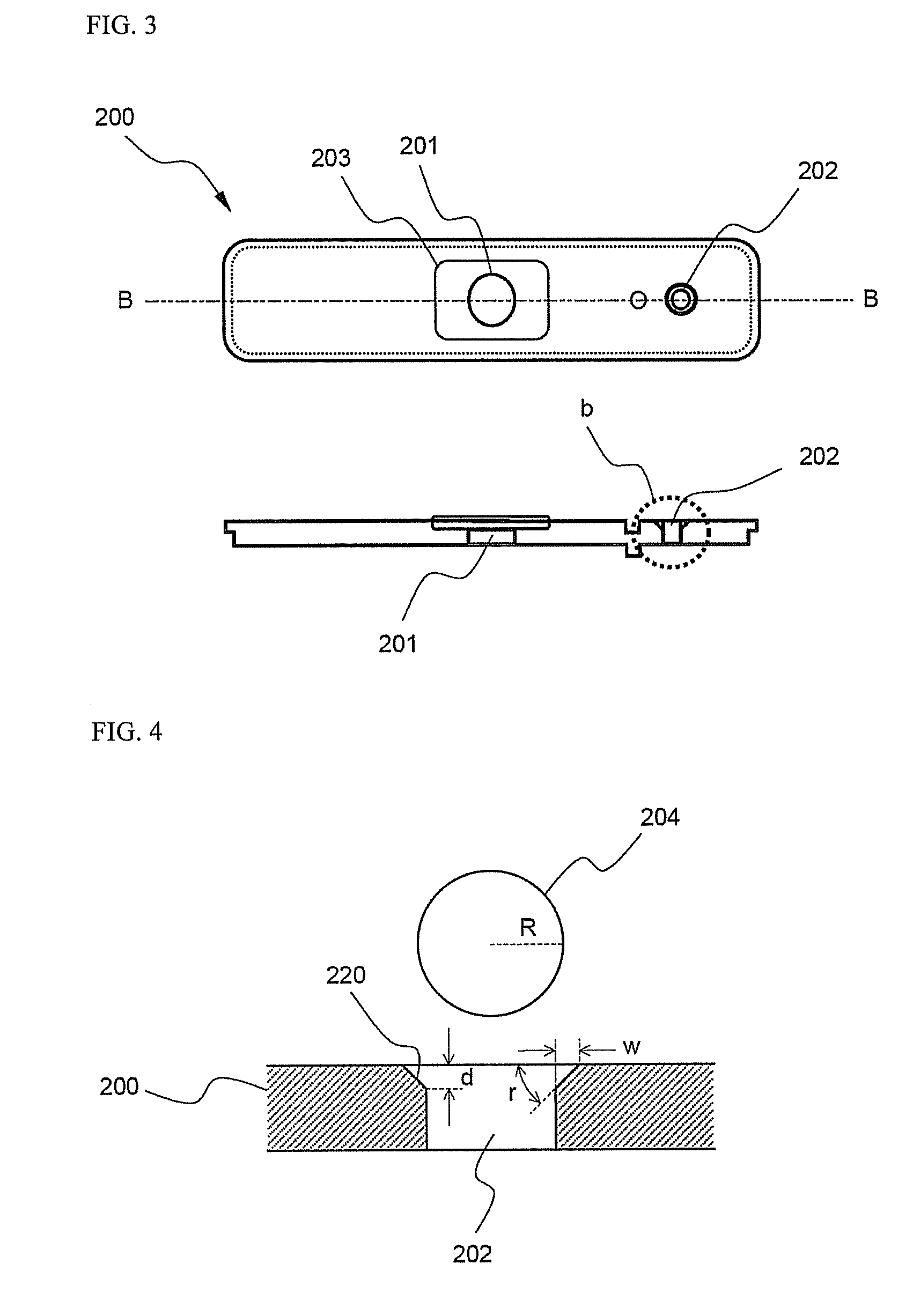
[0011]As a result of a variety of extensive and intensive studies and experiments to solve the problems as described above, the inventors of the present application have discovered that, when an electrolyte injection hole formed in a base plate mounted to the upper end of a battery case is constructed such that the inside upper end of the electrolyte injection hole is formed in a downward taper structure, and a metal ball is forcibly inserted into the electrolyte injection hole so as to plastically deform the metal ball such that the electrolyte injection hole is sealed by the metal ball, the sealability of the electrolyte injection hole is improved due to a high coupling force between the electrolyte injection hole and the plastically deformed metal ball, the formation of a groove, which is caused when the metal ball is plastically deformed according to the conventional art, is effectively prevented, the continuous generation of cracks at the interface between the metal ball and the inside surface of the electrolyte injection hole due to the groove is also effectively prevented, and high electrolyte sealability is accomplished. The present invention has been completed based on the above-mentioned discovery.
[0013]According to the present invention, the inside upper end of the electrolyte injection hole is constructed in the above-described incline structure. Consequently, when the metal ball is forcibly inserted into the electrolyte injection hole (the metal ball is pressed such that the metal ball is inserted into the electrolyte injection hole), the plastic deformation of the metal ball is easily achieved. As a result, the formation of a groove at the upper end of the forcibly inserted metal ball is effectively prevented, the generation of cracks at the interface between the metal ball and the inside surface of the electrolyte injection hole is also effectively prevented, and high electrolyte sealability is accomplished.

Problems solved by technology

The formed groove badly affects the sealing of the electrolyte injection hole by laser welding.
Furthermore, inside cracks are continuously generated along the interface between the metal ball and the inside surface of the electrolyte injection hole due to formation of the groove, and therefore, the sealability of the electrolyte injection hole is lowered.
However, as compared with the case that the sealing member (for example, the metal ball) is plastically deformed to seal the electrolyte injection hole, this sealing structure has problems in that the coupling force between the electrolyte injection hole and the sealing member is small, and therefore, the sealability of the electrolyte injection hole is low.

Method used


Image

  • Prismatic battery having electrolyte injection-hole capable of excellent sealing-disposition
  • Prismatic battery having electrolyte injection-hole capable of excellent sealing-disposition
  • Prismatic battery having electrolyte injection-hole capable of excellent sealing-disposition

Examples


example 1

[0040]An electrolyte injection hole having an inner diameter (a lower-end inner diameter) of 1.2 mm was formed, by drilling, in an aluminum base plate having a thickness of 0.8 mm. An incline structure having an inner diameter (an upper-end inner diameter) and an angle of inclination of approximately 45 degrees was formed at the inside upper end of the base plate by forging. The base plate was fixed to the upper end of an aluminum prismatic battery case by laser welding.

[0041]Subsequently, a predetermined amount of electrolyte was injected into the battery case through the electrolyte injection hole. An aluminum ball having a diameter of 1.37 mm was located on the electrolyte injection hole, and the aluminum ball was forcibly inserted into the electrolyte injection hole with a pressure of 0.4 MPa so as to seal the electrolyte injection hole.

experimental example 1

[0044]FIGS. 5 and 6 are photographs respectively illustrating the plan shape and the sectional shape of the electrolyte injection hole according to Example 1. FIGS. 7 and 8 are photographs respectively illustrating the plan shape and the sectional shape of the electrolyte injection hole according to Comparative Example 1. FIGS. 9 and 10 are photographs respectively illustrating the plan shape and the sectional shape of the electrolyte injection hole according to Comparative Example 2.

[0045]It can be seen from the photographs of the electrolyte injection hole according to Comparative Example 1 that, when the aluminum ball was forcibly inserted into the electrolyte injection hole, a portion of the aluminum ball was plastically deformed and pushed upward along the inside surface of the electrolyte injection hole, and, as a result, a groove corresponding to the shape of the electrolyte injection hole was formed at the upper end of the forcibly inserted ball. It can be also seen that cra...

experimental example 2

[0049]Pressures of electrolyte, when the electrolyte starts to leak, were measured so as to confirm a possibility that the electrolyte leaks through the respective electrolyte injection holes sealed according to Example 1 and Comparative Examples 1 and 2. The measurement results are shown in a graph of FIG. 12.

[0050]As can be seen from FIG. 12, a fairly large pressure is necessary for the electrolyte to leak through the electrolyte injection hole sealed according to Example 1. On the other hand, it can be seen that the electrolyte easily leaks through the electrolyte injection hole sealed according to Comparative Example 1 even when a very small pressure is applied to the electrolyte injection hole.

[0051]Also, it can be seen that the electrolyte injection hole sealed according to Comparative Example 2, in which the inside upper end of the electrolyte injection hole was constructed in the incline structure and the aluminum rivet was used as the sealing member, has a sealing force gre...


PUM

PropertyMeasurementUnit
angleaaaaaaaaaa
angleaaaaaaaaaa
pressureaaaaaaaaaa

Abstract

Disclosed herein is a prismatic battery having an electrode assembly mounted in a prismatic battery case, wherein an electrolyte injection hole formed in a base plate mounted to an open upper end of the battery case is constructed such that an inside upper end of the electrolyte injection hole is formed in a downward taper (incline) structure, and a metal ball is forcibly inserted into the electrolyte injection hole such that the metal ball is plastically deformed to seal the electrolyte injection hole. The prismatic battery according to the present invention provides high coupling force between the metal ball and the electrolyte injection hole due to the plastic deformation and forced insertion of the metal ball and high sealability of the electrolyte injection hole. Also, the formation of a groove at the upper end of the forcibly inserted metal ball and the generation of cracks at the interface between the metal ball and the inside surface of the electrolyte injection hole are effectively prevented. Consequently, the present invention has the effect of accomplishing high electrolyte sealability.

Description

FIELD OF THE INVENTION[0001]The present invention relates to a prismatic battery having a highly sealable electrolyte injection hole, and, more particularly, to a prismatic battery having an electrode assembly mounted in a prismatic battery case, wherein an electrolyte injection hole formed in a base plate mounted to an open upper end of the battery case is constructed such that an inside upper end of the electrolyte injection hole is formed in a downward taper structure, whereby, when a metal ball is forcibly inserted into the electrolyte injection hole so as to plastically deform the metal ball, the formation of a groove at the upper end of the forcibly inserted metal ball and the generation of cracks at the interface between the metal ball and the inside surface of the electrolyte injection hole are effectively prevented, and therefore, high electrolyte sealability is accomplished.BACKGROUND OF THE INVENTION[0002]As mobile devices have been increasingly developed, and the demand ...

Claims


Application Information

Patent Timeline
Patent Type & Authority Patents(United States)
IPC IPC(8): H01M2/08H01M2/00H01M2/36H01M50/627H01M50/636
CPCH01M2/0404H01M2/0473H01M2/0486H01M2/361H01M2/365Y02E60/10H01M50/15H01M50/636H01M50/627H01M50/103H01M50/155H01M50/183H01M50/60
Inventor YEO, CHANG-SINKWON, SUNG RYULKIM, HYUNJINLEE, SEUNG TAEJEON, JIN-WOO
Owner LG ENERGY SOLUTION LTD
Learn More