Eureka AIR delivers breakthrough ideas for toughest innovation challenges, trusted by R&D personnel around the world.

Frame mounted hose clamp

a clamping and frame technology, applied in the direction of machine supports, other domestic objects, mechanical apparatus, etc., can solve the problems of stubs being bent, structure easily broken or bent, and difficult replacement, so as to reduce or eliminate the problem of associated problems, the effect of reducing or eliminating the problem

Active Publication Date: 2009-01-20
DEERE & CO
View PDF22 Cites 17 Cited by
  • Summary
  • Abstract
  • Description
  • Claims
  • Application Information

AI Technical Summary

Benefits of technology

[0008]It is another object to provide an improved hose support clamp for an implement, the clamp reducing or eliminating problems associated with stripped threads. It is yet another object to provide such a clamp that eliminates a threaded piece fixed to the frame. It is still a further object to provide such a clamp having a cavity that allows the head of a support bolt to simply be slid in and out of the clamp portion fixed to the frame.
[0009]It is a further object to provide an improved hose support clamp that is lower in cost and more reliable than many other designs and can be used for multiple functions.
[0010]It is a further object of the present invention to provide an improved hose support clamp that is able to hold multiple hoses, is low in cost, and is easy to paint and weld. It is also an object to provide such a clamp that is easy to use, is reliable, does not require a critical bolt length, and has a threaded part that is easy to replace if stripped.
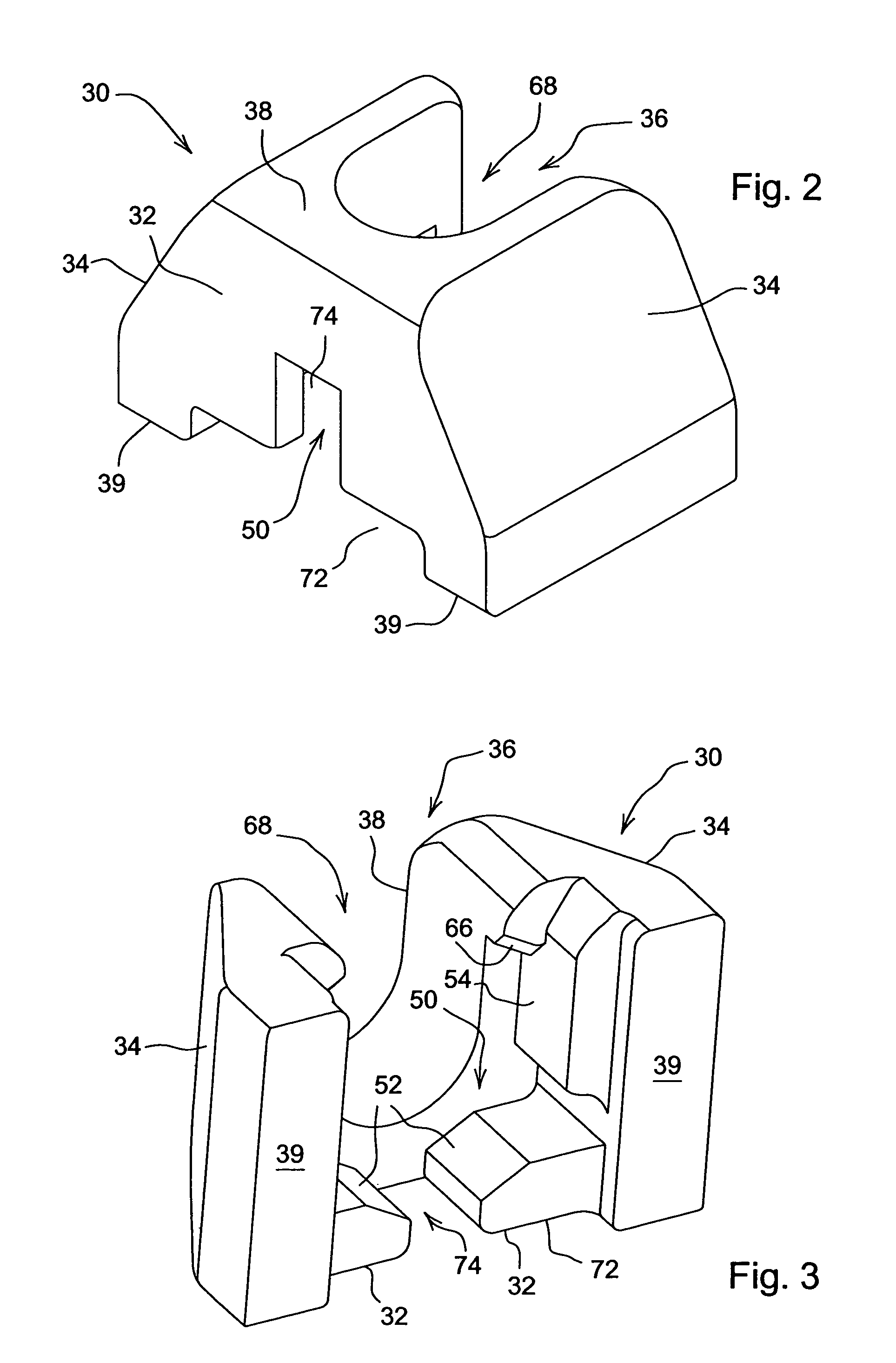
[0011]A hose support clamp assembly includes a threadless retainer connected to the implement frame or other member on the implement. The retainer includes a hex cavity opening outwardly from a first side of the retainer. The second side of the cavity also opens to allow paint drainage during manufacture. The headed end of a hex bolt is slid through the first side into the cavity. A clamping member such as a P-clamp is placed over the projecting threaded end and includes a downwardly directed portion abutting the side of the retainer opposite the first side to prevent the bolt from sliding out of the cavity. A nut is secured on the threaded end to maintain the support clamp in position.
[0012]The support clamp assembly is supports the threaded member for quick and easy replacement without direct connection of the threaded member to the frame. The retainer is easy to weld and paint and reduces paint drip problems. The entire assembly is simple and inexpensive in construction and eliminates need for a precise bolt length. The bolt support function of the clamp prevents lost hardware and hose support failure if the bolt and nut loosen. The retainer also functions as a connector for other hardware mounted on an implement frame.

Problems solved by technology

Such structure can be easily broken or bent as the frame is assembled.
Replacement is difficult once the stubs are bent or broken.
If threads strip, the clamp is rendered useless.
Hoses that are not secured properly can move and wear against the clamp structure.
If pulled out away from the frame component, the hoses are more vulnerable to damage.
However, because of the limited hose capacity of the clamp, numerous clamps have to be stacked or spread out on the frame.
Such two-hose designs often utilize a threaded plate with a bolt, and the bolt length is critical.
The threads in a threaded plate can easily strip and make the clamp unusable.
With such a design, bolt length is critical.
Once the threads are stripped, a nut is usually placed on the under side of the plate to receive a bolt, a process which is inconvenient and time consuming.
In addition, if the hose clamp loosens, an edge of the channel can cut the hose.

Method used


Image

  • Frame mounted hose clamp
  • Frame mounted hose clamp
  • Frame mounted hose clamp

Examples


Embodiment Construction

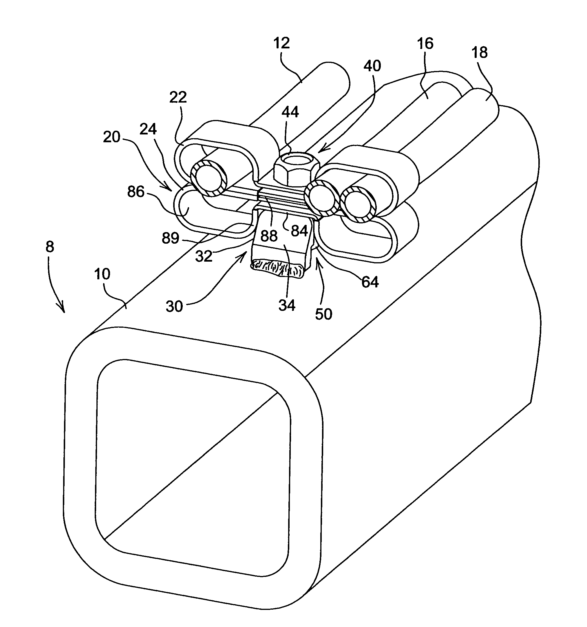
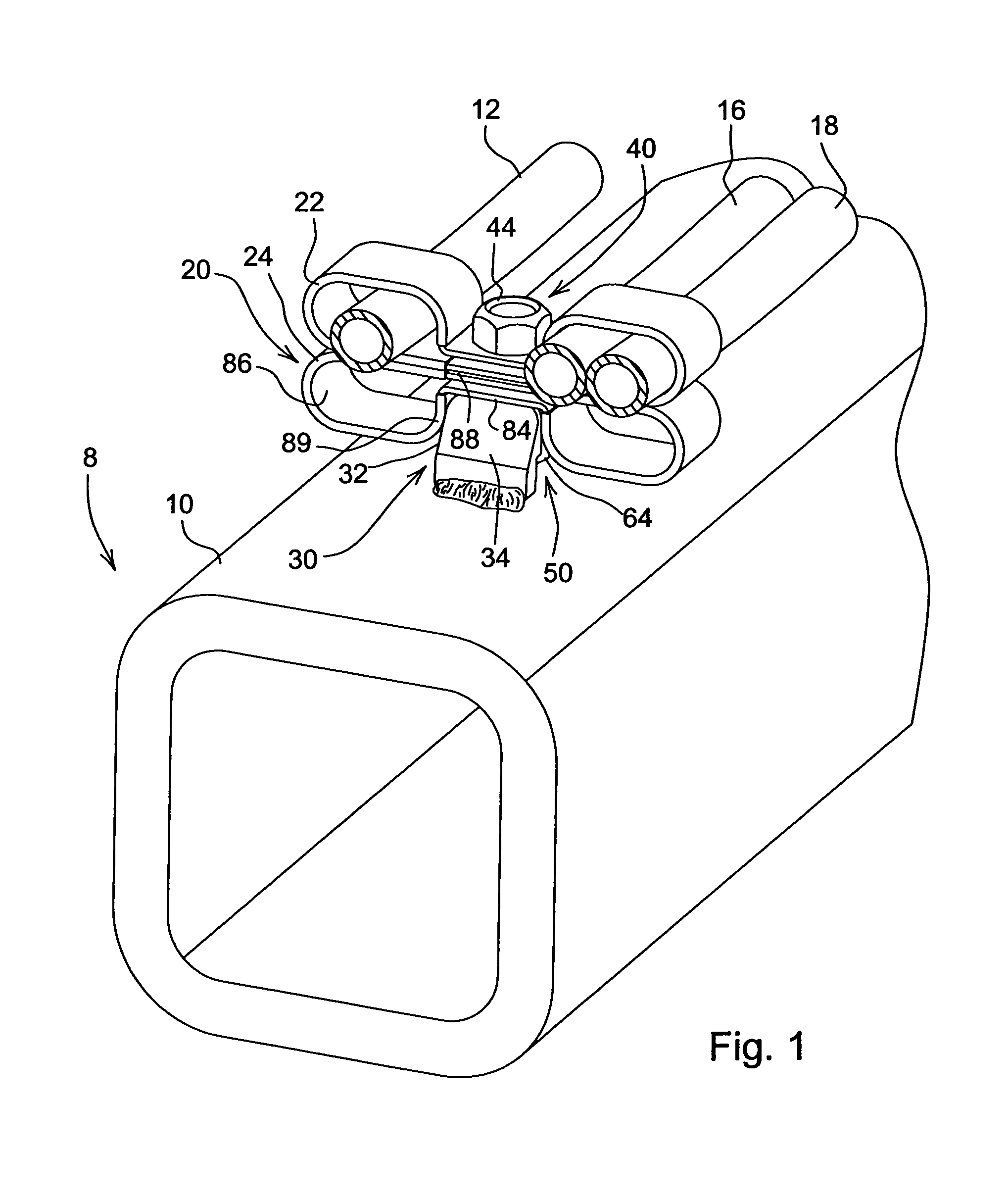
[0017]Referring to FIG. 1, therein is shown a portion of an agricultural implement 8 having a frame 10 supporting lines 12, 16 and 18 or similar conduits, conductors or hoses. The lines 12-18 as shown are hydraulic fluid lines connected between a source of hydraulic fluid (not shown) on a tractor or towing vehicle and a hydraulic motor. To protect the lines 12-18 and maintain the lines away from interference with other portions of the implement and with plant material and the like, hose clamp retainer assemblies, one of which is shown at 20, are mounted on the frame 10 at spaced locations to secure the lines in position on the frame 10. Typically, the retainer assemblies 20 maintain lengths of the lines 12-18 generally parallel to the frame 10.

[0018]The hose clamp retainer assembly 20 as shown in FIG. 1 includes first and second P-clamps 22 and 24 supported on a one-piece retainer 30. The retainer 30 is welded to one face of the frame 10 or other support area on the implement 8.

[001...


PUM


Abstract

A hose clamp retainer assembly for an implement includes a retainer welded to the implement and having an apertured wall leading into a cavity. A bolt having a headed end is slidably received within through the apertured wall for support within the cavity. A hose clamp received by the bolt includes a projecting portion abutting the second wall and preventing the headed end from sliding out of the cavity through the apertured wall. The bolt can be easily replaced if damaged.

Description

FIELD OF THE INVENTION[0001]The present invention relates generally to line supports for agricultural implements and, more specifically, to clamps for hydraulic or electrical lines.BACKGROUND OF THE INVENTION[0002]Various clamp structures are provided on implement frames to secure hydraulic hoses or other lines to the frames. One type of structure includes threaded stubs welded directly to a frame component. Such structure can be easily broken or bent as the frame is assembled. Replacement is difficult once the stubs are bent or broken. If threads strip, the clamp is rendered useless.[0003]Typically, the hoses are held in protective alignment with frame components by straps, and if the hoses have differing diameters, the smaller hoses will be loose when the larger hoses are properly secured. Hoses that are not secured properly can move and wear against the clamp structure. If pulled out away from the frame component, the hoses are more vulnerable to damage.[0004]Some two-hose design...

Claims


Application Information

Patent Timeline
Patent Type & Authority Patents(United States)
IPC IPC(8): F16L3/08F16L3/12
CPCF16L3/223F16L3/24
Inventor ROYER, ANTHONY SCOTT
Owner DEERE & CO
Why Eureka
Eureka Blog
Learn More