Gating voltage control system and method for electrostatically actuating a micro-electromechanical device

a micro-electromechanical device and control system technology, applied in the field of circuitry for actuating a micro-electromechanical device, can solve the problems of uncomplicated implementation of the control system for the voltage source, introduce undesirable effects, electrostatic actuation, etc., and achieve the effect of reducing the amount of for

Active Publication Date: 2009-01-06
GENERAL ELECTRIC CO
View PDF3 Cites 6 Cited by
  • Summary
  • Abstract
  • Description
  • Claims
  • Application Information

AI Technical Summary

Benefits of technology

[0008]Generally, in one aspect thereof, the present invention provides a gating voltage control system for electrostatically actuating a micro-electromechanical systems (MEMS) switch. The switch may comprise an electrostatically responsive actuator movable through a gap for actuating the switch to a respective switching condition corresponding to one of a closed switching condition and an open switching condition. The control system comprises a drive circuit electrically coupled to a gate terminal of the switch to apply a gating voltage. The control system further comprises a controller electrically coupled to the drive circuit to control the gating voltage applied to the gating terminal in accordance with a gating voltage control sequence. The gating voltage control sequence may comprise a first interval for ramping up the gating voltage to a voltage level for producing an electrostatic force sufficient to accelerate the actuator through a portion of the gap to be traversed by the actuator to reach a respective switching condition. The gating voltage control sequence may further comprise a second interval for ramping down the gating voltage to a level sufficient to reduce the electrostatic force acting on the movable actuator. This allows reducing the amount of force at which the actuator engages a switch contact for establishing a closed switching condition, or avoiding an overshoot position of the actuator while reaching an open switching condition.
[0009]In another aspect thereof, the present invention provides a gating voltage control system for electrostatically actuating a micro-electromechanical systems (MEMS) device. The device may comprise an electrostatically responsive actuator movable through a gap for actuating the device to a respective actuating condition corresponding to one of a first actuating condition and a second actuating condition. The gating voltage control system may comprise a drive circuit electrically coupled to a gate terminal of the device to apply a gating voltage. The gating voltage control system may further comprise a controller electrically coupled to the drive circuit to control the gating voltage applied to the gating terminal in accordance with a gating voltage control sequence. The gating voltage control sequence may comprise a first interval for ramping up the gating voltage to a voltage level for producing an electrostatic force sufficient to accelerate the actuator through a portion of the gap to be traversed by the actuator to reach a respective actuating condition. The gating voltage control sequence may further comprise a second interval for ramping down the gating voltage to a level sufficient to reduce the electrostatic force acting on the movable actuator. This allows reducing the amount of force at which the actuator engages a contact for establishing the first actuating condition, or avoiding an overshoot position of the actuator while reaching the second actuating condition.

Problems solved by technology

The implementation of the control for the voltage source tends to be uncomplicated for this type of electrostatic actuation.
It is also known that this form of electrostatic actuation (e.g., step function) may introduce undesirable effects either during a switch closing event or a switch opening event.
As a result, the cantilever beam greatly accelerates as it approaches the contact and may impact the contact with a substantial force (e.g., high speed impact).
Some approaches to solve the high speed impact (and concomitant) bouncing have generally involved cumbersome and costly approaches that can affect the structural design of the MEMS device, e.g., changing the physical dimensions and / or material of the beam to make it stiffer, changing the atmosphere where the switch operates, using a dampening structure, etc.
However, this tends to increase the switch actuation time to an unacceptable level.
Another consequence of a high speed impact is a tendency to rapidly degrade the switch contacts over time.
The number of operational cycles that a switch is rated to perform over its lifetime is often limited by the wearing of the contacts.
During a moment when the switch falls below its rated standoff voltage, this may cause the voltage standoff to be less than the required dielectric isolation with respect to the source (load) voltage and may lead to an undesirable arcing (voltage breakdown) condition, or to a momentary re-closure due to electrostatic attraction.

Method used


Image

  • Gating voltage control system and method for electrostatically actuating a micro-electromechanical device
  • Gating voltage control system and method for electrostatically actuating a micro-electromechanical device
  • Gating voltage control system and method for electrostatically actuating a micro-electromechanical device

Examples


Embodiment Construction

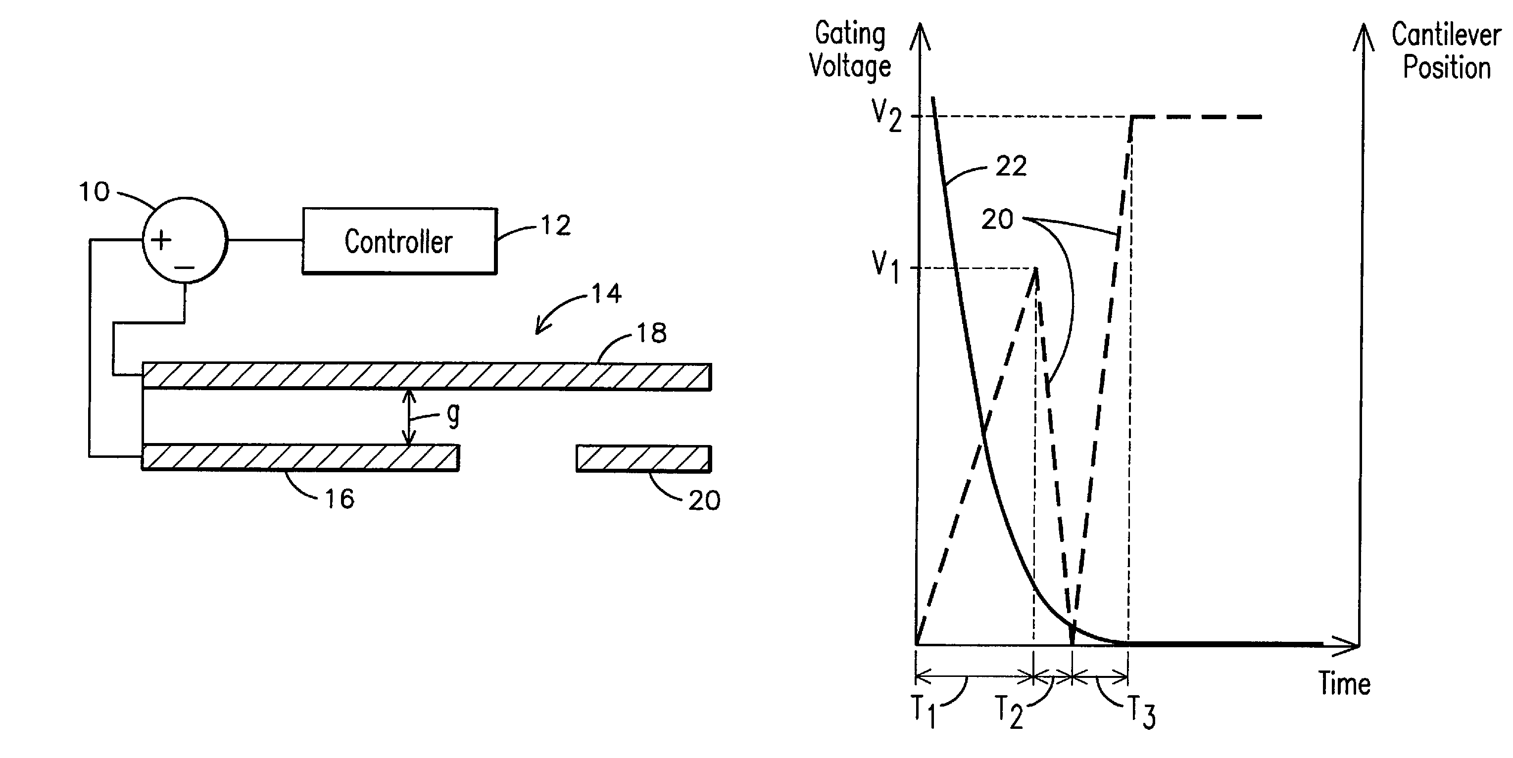
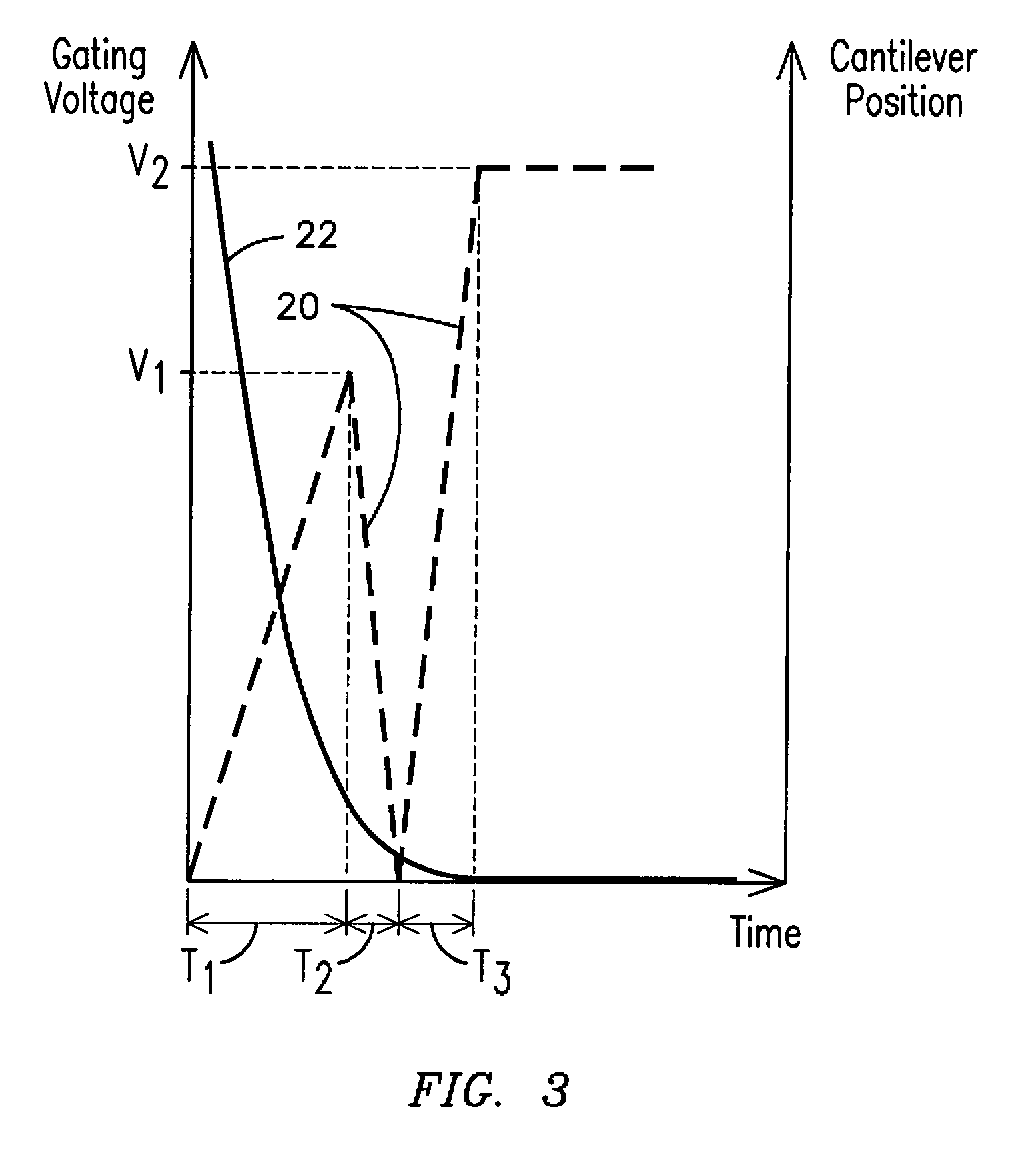
[0014]In accordance with embodiments of the present invention, structural and / or operational relationships, as may be used to provide gating voltage control (e.g., to meet a desired switching condition), such as for a switching array based on micro-electromechanical systems (MEMS) switches are described herein. Presently, MEMS generally refer to micron-scale structures that for example can integrate a multiplicity of functionally distinct elements, e.g., mechanical elements, electromechanical elements, sensors, actuators, and electronics, on a common substrate through micro-fabrication technology. It is contemplated, however, that many techniques and structures presently available in MEMS devices will in just a few years be available via nanotechnology-based devices, e.g., structures that may be smaller than 100 nanometers in size. Accordingly, even though example embodiments described throughout this document may refer to MEMS-based devices, it is submitted that the inventive aspec...


PUM


Abstract

A gating voltage control system and method are provided for electrostatically actuating a micro-electromechanical systems (MEMS) device, e.g., a MEMS switch. The device may comprise an electrostatically responsive actuator movable through a gap for actuating the device to a respective actuating condition corresponding to one of a first actuating condition (e.g., a closed switching condition) and a second actuating condition (e.g., an open switching condition). The gating voltage control system may comprise a drive circuit electrically coupled to a gate terminal of the device to apply a gating voltage. The gating voltage control system may further comprise a controller electrically coupled to the drive circuit to control the gating voltage applied to the gating terminal in accordance with a gating voltage control sequence. The gating voltage control sequence may comprise a first interval for ramping up the gating voltage to a voltage level for producing an electrostatic force sufficient to accelerate the actuator through a portion of the gap to be traversed by the actuator to reach a respective actuating condition. The gating voltage control sequence may further comprise a second interval for ramping down the gating voltage to a level sufficient to reduce the electrostatic force acting on the movable actuator. This allows reducing the amount of force at which the actuator engages a contact for establishing the first actuating condition, or avoiding an overshoot position of the actuator while reaching the second actuating condition.

Description

FIELD OF THE INVENTION[0001]The present invention is generally related to circuitry for actuating a micro-electromechanical systems (MEMS) device, and, more particularly, to a gating voltage control system and method for electrostatically actuating a MEMS switch.BACKGROUND OF THE INVENTION[0002]It is known to provide electrostatic actuation in micro-electromechanical systems (MEMS) devices that may include an actuator (e.g., a cantilever beam) responsive to such electrostatic actuation. For example, in MEMS switches the electrostatic actuation generally occurs by applying a voltage from a voltage source between a gate terminal and a source terminal in a three terminal device; or between the gate terminal and gate ground for four terminal devices. The actuation voltage can range from approximately 3V to approximately >100V and may be typically applied as a step function, or a realizable approximation of a step function.[0003]For example, when the step function voltage is low (e.g....

Claims


Application Information

Patent Timeline
Patent Type & Authority Patents(United States)
IPC IPC(8): H01H51/22
CPCH01H59/0009H01H47/22H01H59/00
Inventor WRIGHT, JOSHUA ISAACSUBRAMANIAN, KANAKASABAPATHIPREMERLANI, WILLIAM JAMESPARK, JOHN NORTONKEIMEL, CHRISTOPHERQUE, LONGRAMA KISHORE, KUNA VENKAT SATYASATHE, ABHIJEET DINKARWANG, XUEFENGHOWELL, EDWARD KEITH
Owner GENERAL ELECTRIC CO
Why Eureka
Try Eureka