
Advanced adaptive pre-distortion in a radio frequency transmitter

a radio frequency transmitter and adaptive technology, applied in the field of communication systems, can solve the problem that conventional systems do not fully utilize the dynamic range of analog-to-digital converters to capture the error component of down-converted samples, and achieve the effect of reducing quantization steps, reducing cost, and increasing linearity

Inactive Publication Date: 2008-12-30
MAXLINEAR ASIA SINGAPORE PTE LTD
View PDF22 Cites 43 Cited by
  • Summary
  • Abstract
  • Description
  • Claims
  • Application Information

AI Technical Summary

Benefits of technology

This approach improves the linearity of RF transmitters by effectively utilizing ADC dynamic range, reducing distortion, and allowing for cost-effective solutions with equivalent performance, while maintaining or improving the cancellation of nonlinearities across a wide bandwidth.

Problems solved by technology

As the main signal component is a substantial component of the magnitude of the down-converted sample, conventional systems do not fully utilize the dynamic range of the analog-to-digital converter to capture the error component of the down-converted sample.

Method used


Image

  • Advanced adaptive pre-distortion in a radio frequency transmitter
  • Advanced adaptive pre-distortion in a radio frequency transmitter
  • Advanced adaptive pre-distortion in a radio frequency transmitter

Examples


Embodiment Construction

[0025]Although this invention will be described in terms of certain preferred embodiments, other embodiments that are apparent to those of ordinary skill in the art, including embodiments which do not provide all of the benefits and features set forth herein, are also within the scope of this invention. Accordingly, the scope of the present invention is defined only by reference to the appended claims.

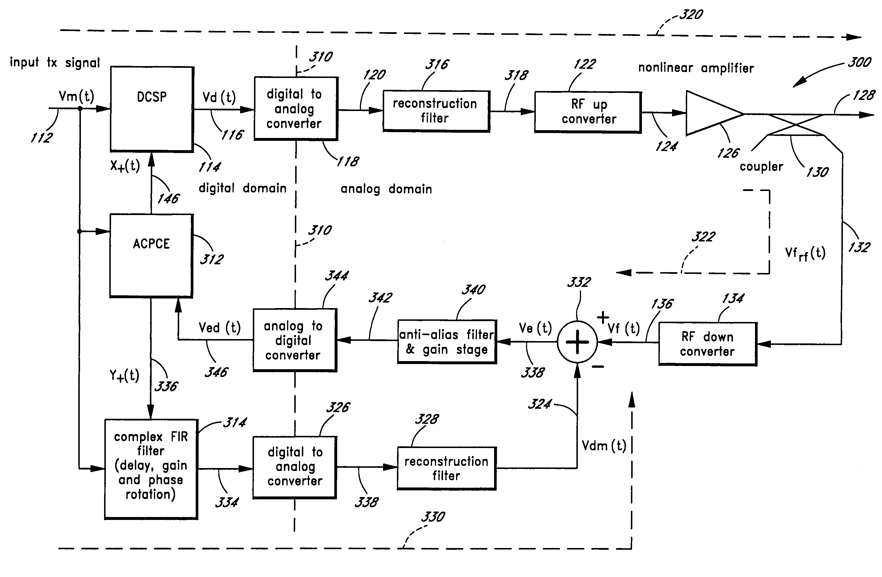
[0026]Embodiments of the present invention advantageously allow the efficient use of the dynamic range of an analog-to-digital converter (ADC) used to sample the output signal in an RF transmitter with an adaptive predistortion linearization circuit. In one embodiment, the efficient use of the dynamic range of the ADC enhances the linearity of the RF transmitter. In another embodiment, the efficient use of the dynamic range of the ADC allows a substitution of a less expensive ADC with no decrease in performance. These two benefits can be appropriately combined to achieve a desired cost...


PUM


Abstract

The present invention is related to methods and apparatus that advantageously permit the more efficient use of an input range of an analog-to-digital converter used by an adaptive predistortion linearized RF transmitter. A main signal component of a down-converted output of an RF transmitter is removed prior to the analog-to-digital conversion of the down-converted output, thereby allowing more of the input range of the analog-to-digital converter to capture an error signal component of the down-converted output. Embodiments of the present invention can thus adaptively tune the predistortion stage to a higher degree of linearity or can use lower cost analog-to-digital converters with fewer quantization steps for the same performance.

Description

CROSS-REFERENCE TO RELATED APPLICATIONS[0001]This application is a continuation application of U.S. Application Ser. No. 09 / 764,680, filed Jan. 18, 2001, now U.S. Pat. No. 6,973,138 B1, which claims the benefit under 35 U.S.C. § 119(e) of U.S. Provisional Application No. 60 / 178,207, filed Jan. 26, 2000, the disclosures of which are hereby incorporated by reference in their entireties herein.BACKGROUND OF THE INVENTION[0002]1. Field of the Invention[0003]The present invention is generally related to communications systems. In particular, the present invention relates to linearizing Radio Frequency (RF) power amplifiers.[0004]2. Description of the Related Art[0005]Radio Frequency (RF) power amplifiers prepare a signal for transmission by increasing the power of the signal. The signal, such as a television signal, radio signal, or cell phone signal, can be transmitted through the air via an antenna. Other signals, such as those found in cable-TV systems, are transmitted through cables....

Claims


Application Information

Patent Timeline
Patent Type & Authority Patents(United States)
IPC IPC(8): H04L25/49H03C1/06H03F1/26H04B1/04H04L25/03H04L27/36
CPCH04L27/368
Inventor WRIGHT, ANDREW S.
Owner MAXLINEAR ASIA SINGAPORE PTE LTD
Learn More