
Emergency lighting

a technology for emergency lighting and batteries, applied in emergency power supply arrangements, lighting and heating apparatus, instruments, etc., can solve the problem of relatively high cost of storage batteries, and achieve the effect of simple overvoltage protection and effective control of charging the storage condenser

Inactive Publication Date: 2008-12-16
SIEMENS AG
View PDF23 Cites 13 Cited by
  • Summary
  • Abstract
  • Description
  • Claims
  • Application Information

AI Technical Summary

Benefits of technology

[0006]One object of the invention is to provide a simple, reasonably priced and maintenance-free emergency lighting unit that will be particularly suitable for switch cabinets and fuse boxes, and so forth.
[0008]The emergency lighting according to the invention is practically maintenance-free, inexpensive and can be housed in such a switch cabinet without any problems and without any need for any special measures in the fuse box as such; adequate illumination time is provided also when the device is housed in a standardized small housing.
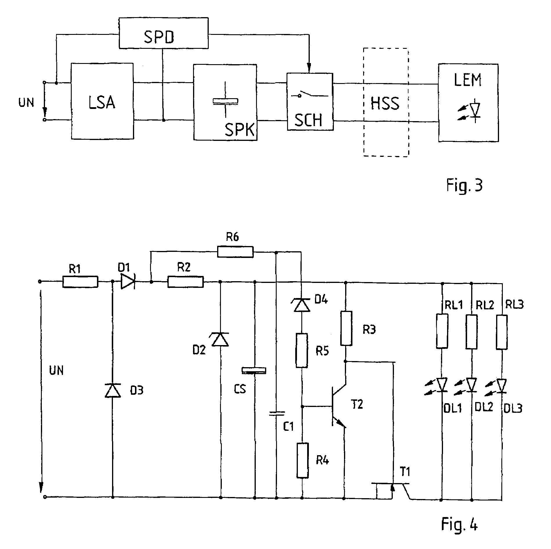
[0009]Although the condenser could be connected to the illuminant also via a relay, it is advantageous that at least one storage condenser can be connected via an electronic switch to the illuminant where the switch is controlled by a power-supply detection circuit.
[0011]It is furthermore practical when the illuminant has at least one light-emitting diode because, along with the high efficiency, light-emitting diodes also have a very long service life.
[0013]In the case of alternating-voltage power grids, it is advisable to place a rectifier diode between the protective resistor and at least one storage condenser in order to obtain a direct voltage in a simple manner. If the point of connection between the protective resistor and the rectifier diode is connected with the other pole of the alternating voltage via an auxiliary diode that is poled opposite to the rectifier diode, then one gets a simple overvoltage protection because, in this case, overvoltages are wiped out in the protective resistor, which is more voltage-stable than the semiconductor components. This provides a simple possibility for displaying the operating state when a light-emitting diode is connected in series with the auxiliary diode to display the alternating operating voltage.

Problems solved by technology

In this connection, it must be noted that the use of storage batteries is relatively expensive and frequently requires maintenance, so that emergency lighting is often dispensed with, provided it is not prescribed by law.

Method used


Image

  • Emergency lighting
  • Emergency lighting
  • Emergency lighting

Examples


Embodiment Construction

[0025]In the drawings, like numerals indicate like elements throughout. In the drawings, like numerals indicate like elements throughout. Certain terminology is used herein for convenience only and is not to be taken as a limitation on the present invention. The terminology includes the words specifically mentioned, derivatives thereof and words of similar import. The embodiments illustrated below are not intended to be exhaustive or to limit the invention to the precise form disclosed. These embodiments are chosen and described to best explain the principle of the invention and its application and practical use and to enable others skilled in the art to best utilize the invention.

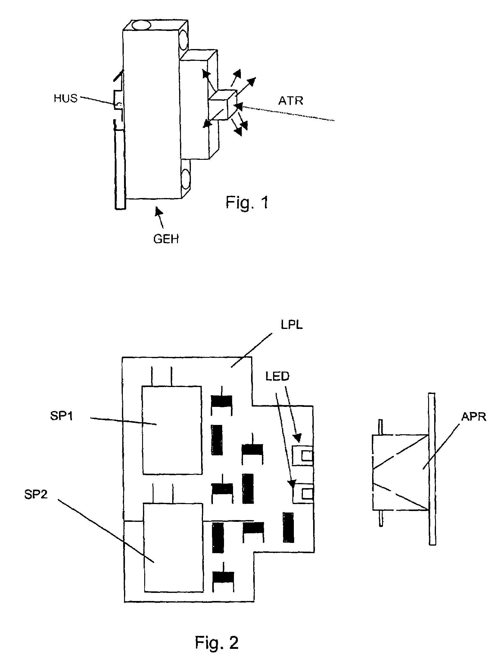
[0026]FIG. 1 shows a possible mechanical structure of an emergency lighting device according to the invention where the circuit of the emergency lighting is in a housing GEH that is capable of accepting top-hot rails, that is to say, that, like the customary safety cutouts or fault-current switches, can be...


PUM


Abstract

An emergency lighting with an electrical illuminant (DL1, DL2, DL3), which, as a power supply drops below a predeterminable value, can be connected to an energy source that can be charged from the power supply by means of a charging connection, for example, by means of an electronic switch (T1), where the energy source consists of at least one high-capacity storage condenser (CS; CS1, CS2) and where light-emitting diodes can be provided as illuminants.

Description

CROSS-REFERENCE TO RELATED APPLICATIONS[0001]This application claims the benefit of PCT Application No. PCT / AT2004 / 000066 filed Mar. 3, 2004 which in turn claims priority from Austrian Patent Application No. A 369 / 2003 filed Mar. 10, 2003.FIELD OF THE INVENTION[0002]This invention relates to emergency lighting with an electrical illuminant, which, as the power supply drops below a predetermined value, can be connected from the power supply to an energy source that can be charged by means of a charging connection.BACKGROUND OF THE INVENTION[0003]In case of power failure, emergency lighting should produce mostly locally limited light for a limited period of time in order, for example, to help people get oriented and to make it possible to initiate certain measures. By “power grid” we mean here primarily alternating-voltage power grids with, for example, 230 V, but also direct-voltage power grids with voltages of, for example, 24 or 48 V.[0004]Emergency lighting is often prescribed by ...

Claims


Application Information

Patent Timeline
Patent Type & Authority Patents(United States)
IPC IPC(8): H05B37/00H02J9/06
CPCH02J9/065
Inventor SCHWEIGERT, HARALD
Owner SIEMENS AG
Learn More