
Aerodynamic insert for high speed permanent magnet motor

a permanent magnet motor and insert technology, applied in the direction of dynamo-electric machines, magnetic circuit rotating parts, magnetic circuit shape/form/construction, etc., can solve problems such as windage losses, and achieve the effect of minimizing volume and weight, and minimizing stress on the rotor ribs and cradles

Inactive Publication Date: 2008-12-16
ELLIOTT CO
View PDF21 Cites 27 Cited by
  • Summary
  • Abstract
  • Description
  • Claims
  • Application Information

AI Technical Summary

Benefits of technology

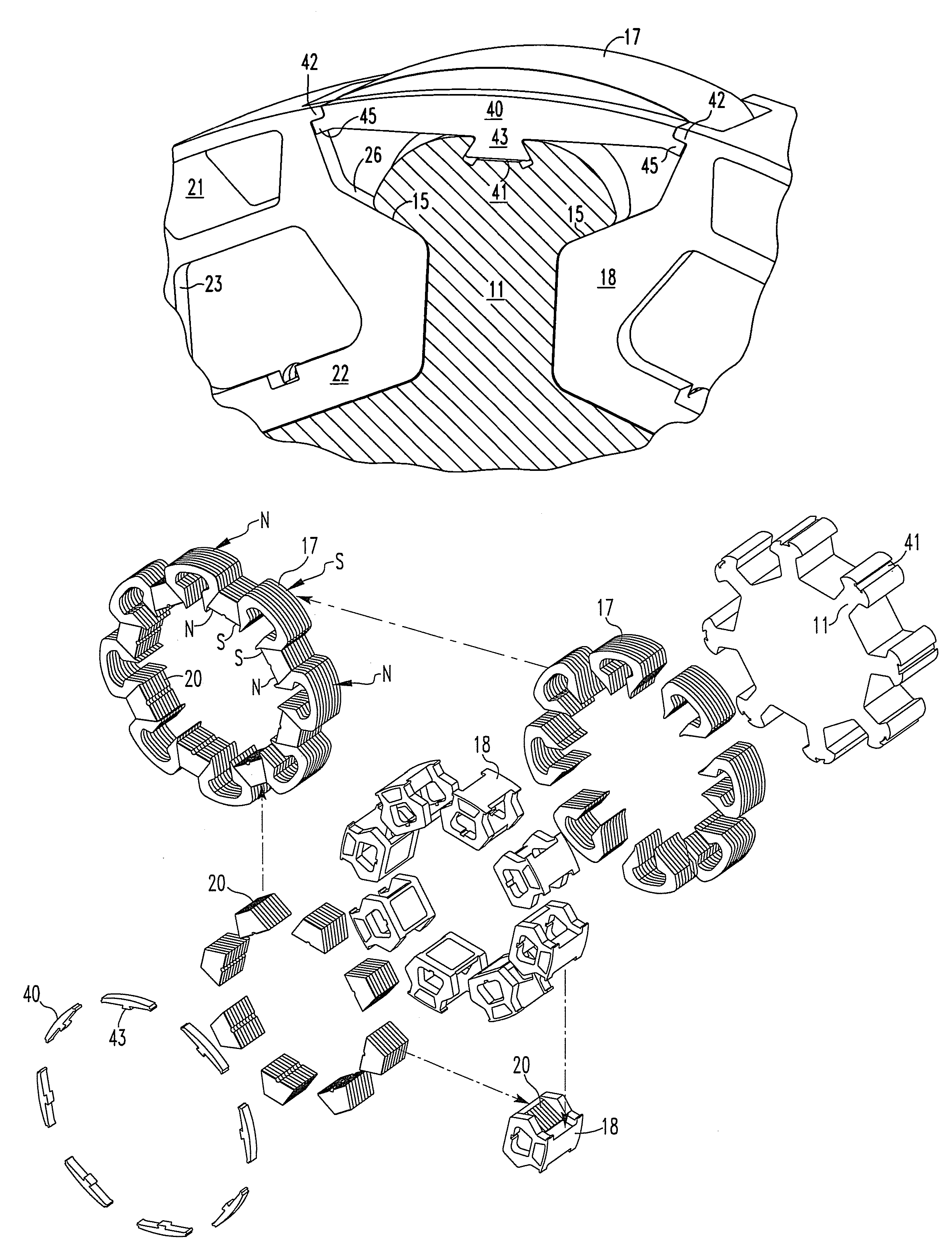
The invention provides a way to secure non-magnetic inserts to a rotor assembly without interfering with its magnetic properties. The inserts are designed to fill the gap between adjacent C-shaped laminations and are secured to the non-magnetic ribs using cradles. The cradles bear directly on the ribs to prevent centrifugal force from affecting the inserts. The non-magnetic inserts are designed to minimize stress on the rotor ribs and cradles. The technical effect of this invention is to improve the performance and reliability of permanent magnet rotor assemblies.

Problems solved by technology

Unfortunately, the fact the axial end walls of the cradles must bear directly upon the ribs leaves a gap between adjacent C-shaped laminations resulting in an uneven assembled rotor surface which results in windage losses.

Method used


Image

  • Aerodynamic insert for high speed permanent magnet motor
  • Aerodynamic insert for high speed permanent magnet motor
  • Aerodynamic insert for high speed permanent magnet motor

Examples


Embodiment Construction

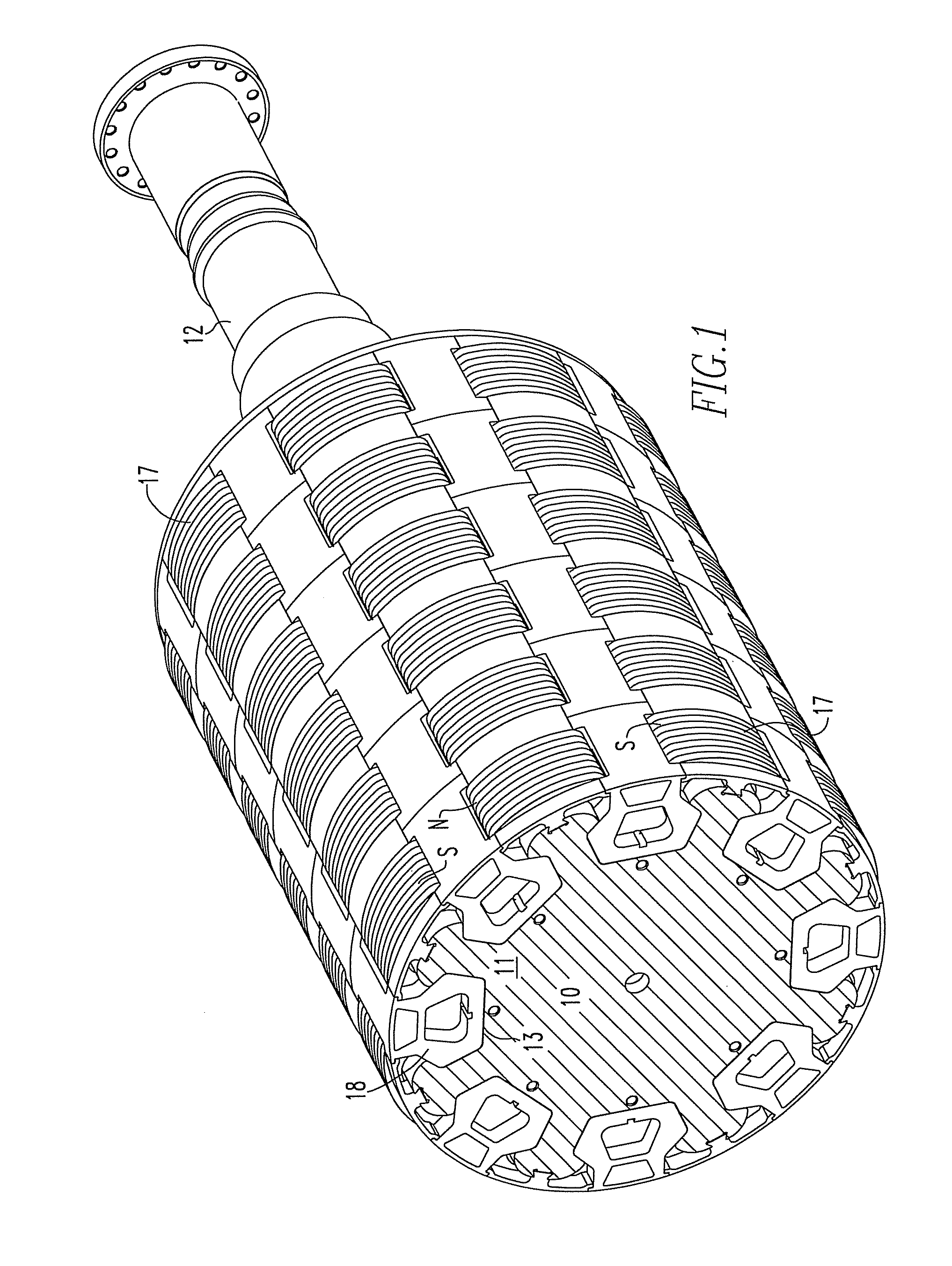
[0016]Referring to FIG. 1, the shaft 10 comprises the foundation of the permanent magnet rotor according to this invention. The shaft 10 is made of non-magnetic high strength material, such as nickel cobalt alloy. The shaft 10 has an interrupted cylindrical surface defined relative to the rotational axis of the rotor. At each end of the shaft, provisions are made for bearings 12. The bearings 12 establish the rotational axis of the rotor. The shaft 10 has an even number of substantially identical recessed and overhung slots 13. The overhung slots 13 define substantially identical generally T-shaped ribs 11 with dovetail surfaces 15 adjacent the slots. The magnets 20, as will be explained, are positioned within the slots held by non-magnetic cradles.

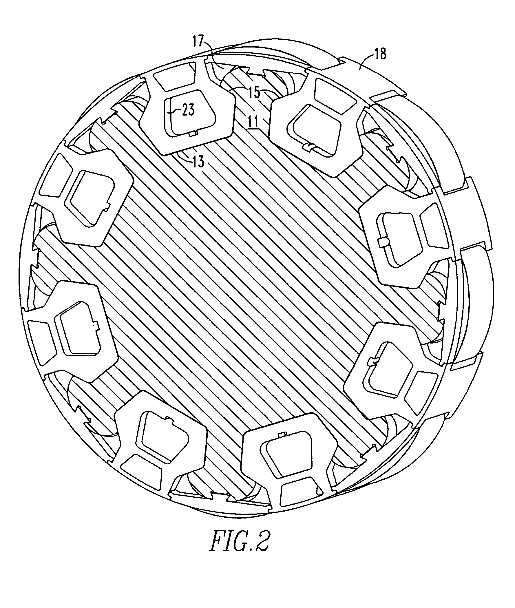
[0017]While the shaft 10 has a continuous cross section (extending axially) in the vicinity of the magnets, it is helpful to consider the shaft in individual sections supporting an even number of magnets. FIG. 2 illustrates such a section...


PUM


Abstract

An insert comprising a lightweight structure configured for filling the gaps between axially spaced C-shaped lamination stacks and circumferentially spaced non-magnetic cradles on a permanent magnet rotor. The insert is secured to a rib by a dovetail tongue that fits within a dovetail groove provided along the length of each rib. The insert engages the adjacent cradles and has a circumferential surface that has the same radius of curvature as the top surface of the cradles.

Description

BACKGROUND OF THE INVENTION[0001]1. Field of the Invention[0002]This invention pertains to high speed, high power permanent magnet electric motors or generators and, in particular, to inserts for installation on the outer surface of the motors or generators for decreasing the windage losses and noise.[0003]2. Description of Related Art[0004]U.S. Pat. No. 6,933,645 entitled “Permanent Magnet Rotor and Magnet Cradle” describes a novel permanent magnet rotor construction for a permanent magnet motor or generator. The rotor assembly comprises a non-magnetic cylindrical shaft having an axis of rotation and a generally cylindrical surface. An even number of recessed and overhung slots in the cylindrical surface define an even number of ribs. C-shaped high magnetic permeability lamination stacks surround the ribs. A permanent magnet is positioned in each recessed slot. The magnets have spaced circumferential end edge faces abutting the lamination stacks. The magnets are magnetized with opp...

Claims


Application Information

Patent Timeline
Patent Type & Authority Patents(United States)
IPC IPC(8): H02K1/27H02K1/28
CPCH02K1/2773
Inventor WATSON, ANDREW P.TAPPER, KEVIN L.
Owner ELLIOTT CO
Learn More