
Image encoder, image encoding method, image decoder, and image decoding method

a decoding method and encoder technology, applied in the field of image encoders, image encoding methods, image decoding methods, etc., can solve the problems of inability to achieve excellent performance and subjective image quality, and achieve the effect of reducing loss of details, and varying the image quality of decoding images

Inactive Publication Date: 2008-12-09
SONY CORP
View PDF8 Cites 30 Cited by
  • Summary
  • Abstract
  • Description
  • Claims
  • Application Information

AI Technical Summary

Benefits of technology

[0016]In the image encoder and image encoding method, and the image decoder and image decoding method according to the present invention, when quantizing each coefficient in each sub-band after filtering processing, the width of the dead zone is varied in correspondence with image quality required. In addition, the predetermined parameter used to perform inverse quantization corresponding to the quantization is included in the encoded code stream. Thus, the image quality of a decoded image can be varied. Particularly, when high quality is required, the width of the dead zone is narrowed to eliminate loss of details caused by quantization, and hence, subjective image quality can be improved.

Problems solved by technology

However, if the encoding bit number is lowered to a certain degree or much lower, block deformation inherent to the DCT appears so conspicuously that subjective deterioration of image quality becomes conspicuous.
There hence has been a problem that excellent performance cannot always be achieved in case where a high-quality image is required at a low compression rate.

Method used


Image

  • Image encoder, image encoding method, image decoder, and image decoding method
  • Image encoder, image encoding method, image decoder, and image decoding method
  • Image encoder, image encoding method, image decoder, and image decoding method

Examples


Embodiment Construction

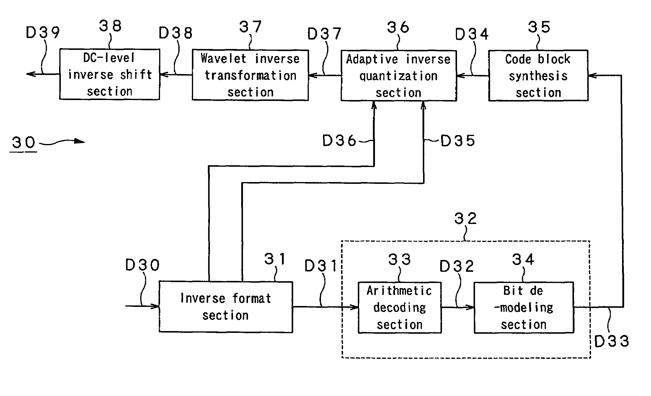
[0031]Hereinafter, a specific embodiment to which the present invention is applied will be described in more details with reference to the drawings. In the present embodiment, the present invention is applied to an image encoder and a method thereof in which an input image is compressed and encoded according to the JPEG 2000 scheme, to generate an encoded code stream, and an image decoder and a method thereof in which the encoded code stream generated is decoded to reconstruct an input image.

[0032](1) Structure and Operation of the Image Encoder

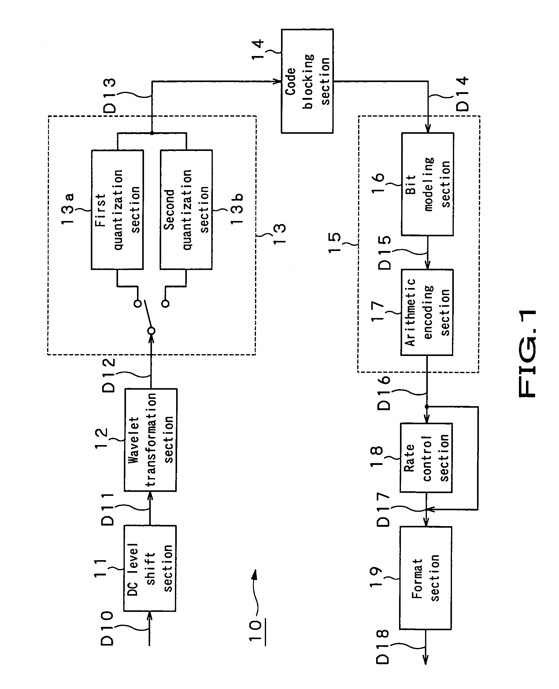
[0033]FIG. 1 shows a schematic structure of the image encoder in the present embodiment. As shown in FIG. 1, the image encoder 10 is constituted by a DC level shift section 11, wavelet transformation section 12, quantization section 13, code blocking section 14, bit modeling section 16, arithmetic encoding section 17, rate control section 18, and format section 19. The quantization section 13 includes a first quantization section 13a selected...


PUM


Abstract

In an image encoder, a first quantization section which is selected when normal image quality is required performs quantization by dividing a wavelet transformation coefficient by a quantization step size and by thereafter rounding down a fraction thereof. On the other side, a second quantization section which is selected when high image quality is required performs quantization by dividing a wavelet transformation coeffient by a quantization step size, by adding 0.5 to the dividing result, and by thereafter rounding down a fraction thereof. Therefore, the width of a dead zone where coefficients are quantized to a value of 0 is narrower than that in the first quantization section, and higher image quality is obtained accordingly.

Description

BACKGROUND OF THE INVENTION[0001]1. Field of the Invention[0002]The present invention relates to an image encoder and a method thereof in which an input image is compressed and encoded by wavelet transformation, quantization, and entropy encoding to generate an encoded code stream, and an image decoder and a method thereof in which the generated code stream is decoded to reconstruct the input image, like the JPEG 2000 scheme.[0003]This application claims priority of Japanese Patent Application NO. 2004-046713, filed on Feb. 23, 2004, the entirety of which is incorporated by reference herein.[0004]2. Description of Related Art[0005]One of conventional typical image compression schemes is the JPEG (Joint Photographic Experts Group) scheme standardized by the ISO (International Standards Organization). This scheme utilizes discrete cosine transformation (DCT). When a relatively high bit number is assigned, excellent encoded and decoded images are obtained, as is known. However, if the ...

Claims


Application Information

Patent Timeline
Patent Type & Authority Patents(United States)
IPC IPC(8): G06K9/36G06K9/46H04N1/41H04N11/02H04N11/04H04N7/12H03M7/30G06T9/00H03M7/40H04N1/413H04N19/34H04N19/60H04N19/635H04N19/85H04N19/91
CPCH04N19/176H04N19/647H04N19/63H04N19/645H04N19/126H04N19/154H04N19/162H04N19/115H04N19/146H04N19/124
Inventor FUKUHARA, TAKAHIROKIMURA, SEIJI
Owner SONY CORP
Learn More