Sensor for measuring carbon dioxide in respiratory gas

a carbon dioxide and sensor technology, applied in the direction of respiratory organ evaluation, valve details, material analysis, etc., can solve the problems of increasing operating costs, difficult connection of the apparatus to the patient, and bulky apparatus, etc., to improve measurement accuracy and responsibility, compact sensor, and less expensive

Active Publication Date: 2008-12-09
NIHON KOHDEN CORP
View PDF34 Cites 12 Cited by
  • Summary
  • Abstract
  • Description
  • Claims
  • Application Information

AI Technical Summary

Benefits of technology

[0046]According to the present invention, there is provided a respiratory gas from a living body can be guided directly to an optical axis of a sensor through a respiratory flow path provided in the sensor. Hence, there is obviated a necessity for an airway adapter and a sampling tube, which have hitherto been employed, thereby rendering the sensor compact and less expensive. Even if one of the nostrils becomes clogged, the concentration of carbon dioxide gas can be detected accurately, thereby improving measurement accuracy and responsibility.
[0047]According to the present inventions, a cylindrical member through which respiratory gas flows and a support member for supporting a light-emitting element and a light-receiving element are formed separately and removably from each other. Hence, production of a cylindrical member is facilitated, as is cleaning of the cylindrical member. Moreover, thin films are hermetically interposed between the cylindrical member and the support member by holding members. Hence, so long as the thin films are formed from a anti-fogging film, occurrence of clouding due to moisture in respiratory gas can be prevented, thereby enabling accurate measurement of concentration of carbon dioxide gas in the respiratory gas.

Problems solved by technology

Hence, difficulty is encountered in connecting the apparatus to a patient to whom no endotracheal tube is attached.
Further, the apparatus is bulky, expensive, and complicated in construction.
Further, the airway adapter 101 must be replaced, thus increasing operating costs.
If the apparatus is designed so as to come into direct contact with the skin, the apparatus will remain in contact with the skin for a long period of time for measurement, thus posing a risk of heat injury.
When the tubing shown in FIG. 17 is used, there arises a problem of the tubing is clogged with moisture in respiratory gas after long-term use.
Further, the detection tube is disposable, thereby adding to operating costs.
Hence, detecting response becomes slow, which in turn deteriorates detection accuracy.
The concentration of carbon dioxide gas in a sampled respiratory gas becomes about one-half the actual concentration in respiratory gas, which in turn may cause an error in measurement.

Method used


Image

  • Sensor for measuring carbon dioxide in respiratory gas
  • Sensor for measuring carbon dioxide in respiratory gas
  • Sensor for measuring carbon dioxide in respiratory gas

Examples


Embodiment Construction

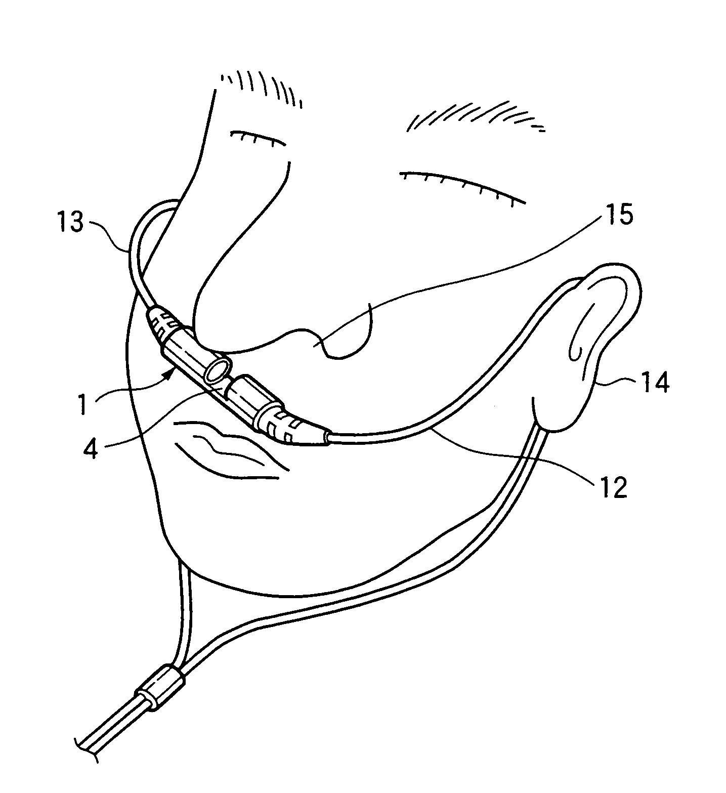
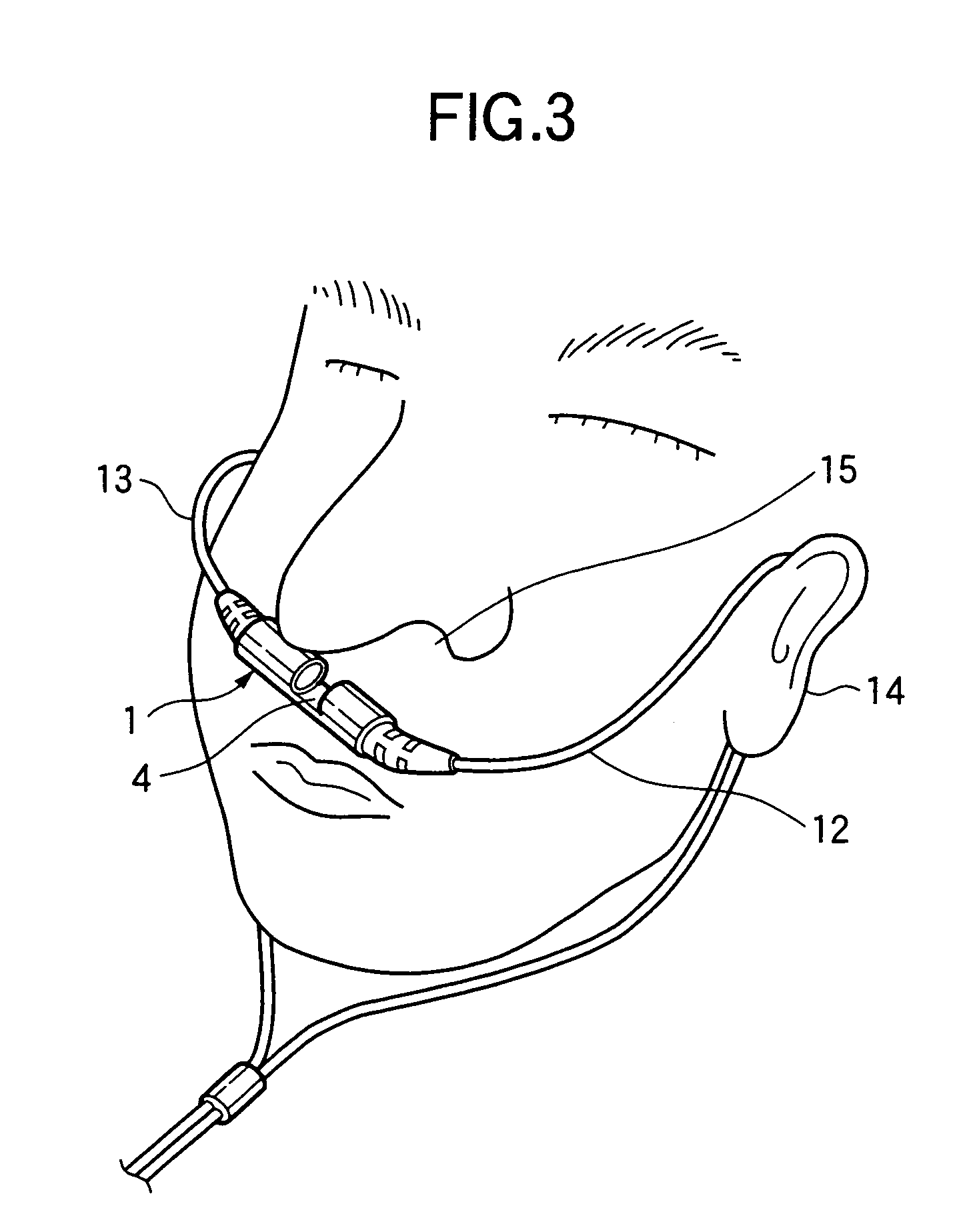
[0072]Embodiments of a sensor for measuring the concentration of a carbon dioxide gas in respiratory gas according to the invention will be described herein below by reference to the accompanying drawings.

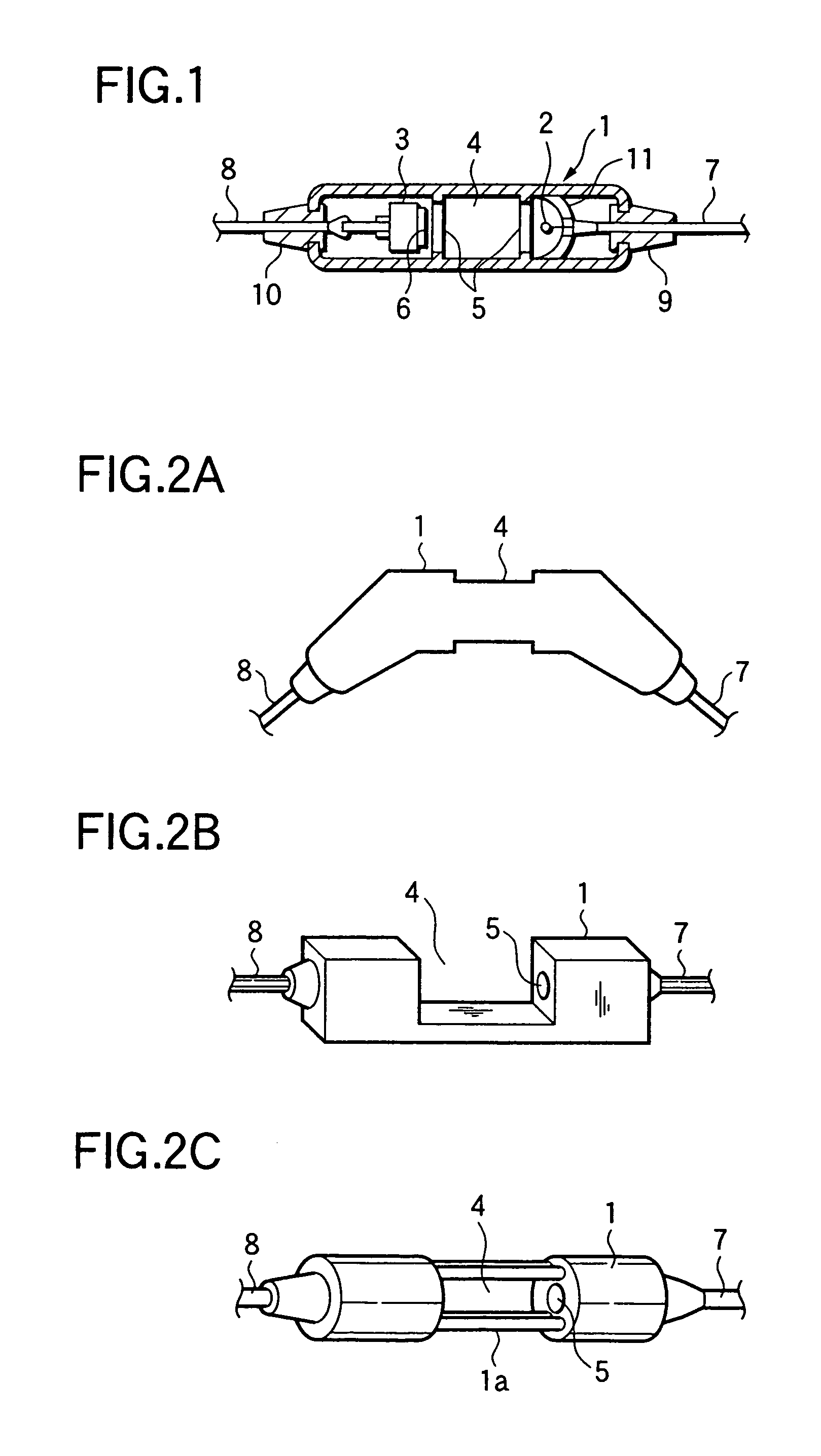
[0073]FIGS. 1 is a transverse cross-sectional view showing an example configuration of a sensor according to a first invention. As shown in FIG. 1, a sensor main unit 1 which is formed from resin or metal into a substantially cylindrical shape and serves as a support member is axially separated into three chambers. A light-emitting element 2 is disposed in a chamber located at one end of the three chambers, and a light-receiving element 3 is disposed in another chamber located at the other end of the three chambers. An respiratory flow path 4 is formed so as to vertically penetrate a middle chamber of the three chambers. The respiratory flow path 4 is hermetically separated from the adjacent two chambers by partitions. An opening section is formed in each of the partitions. A trans...


PUM

PropertyMeasurementUnit
power consumptionaaaaaaaaaa
lengthaaaaaaaaaa
power consumptionaaaaaaaaaa

Abstract

A sensor main unit 1 is axially split into three sub-segments. A light-emitting element 2 is attached to one end portion, and a light-receiving element 3 is attached to the other end portion. A respiratory flow path 4 is formed so as to penetrate through the center portion. The sensor main unit 1 is attached to a position on the face below the nostrils, and respiratory gas from the nostrils is guided into the respiratory flow path 4 and is caused to cross over the optical axis connected the light-emitting element 2 and the light-receiving element 3, thereby measuring a carbon dioxide gas in the respiratory gas.

Description

BACKGROUND OF THE INVENTION[0001]1. Field of the Invention[0002]The present invention relates to a sensor for measuring the concentration or presence / absence of carbon dioxide in respiratory gas through the nostrils or mouth of a living body. More particularly, the invention relates to a simple, compact sensor for measuring carbon dioxide in respiratory gas which can improve the accuracy in measurement and response.[0003]2. Related Art[0004]In general, when the concentration of carbon dioxide contained in respiratory gas from a living body is optically measured, the respiratory gas is caused to pass through a cylindrically-shaped airway adapter. An infrared ray is radiated onto the respiratory gas from a light-emitting element. A voltage corresponding to the amount of light which is absorbed by carbon dioxide contained in the respiratory gas is detected by a light-receiving element, thus measuring the concentration of carbon dioxide.[0005]FIG. 16 shows the schematic configuration of...

Claims


Application Information

Patent Timeline
Patent Type & Authority Patents(United States)
IPC IPC(8): G01N21/00A61L9/00A61M16/00A62B18/02A62B7/00G01N31/00G01N35/00G01N7/00G01N37/00G01N33/00G01N27/00B01J7/00F16K31/02G01N1/22G01N21/35G01N33/497
CPCG01N1/22G01N21/3504G01N33/497G01N33/004A61M16/06A61M16/0666Y10T436/25875G01N2001/2244Y10T436/204998A61M16/085A61M2230/432
Inventor YAMAMORI, SHINJIONO, YOSHINOBUKOJIMA, TAKESHITODOKORO, NORIAKI
Owner NIHON KOHDEN CORP
Why Eureka
Try Eureka