
Vehicle front body structure

a front body and vehicle technology, applied in the direction of roofs, transportation items, transportation and packaging, etc., can solve the problems of increasing the size of the vehicle body, and achieve the effects of reducing the weight increasing the size of the vehicle body, and effective lateral load

Active Publication Date: 2008-12-09
HONDA MOTOR CO LTD
View PDF11 Cites 35 Cited by
  • Summary
  • Abstract
  • Description
  • Claims
  • Application Information

AI Technical Summary

Benefits of technology

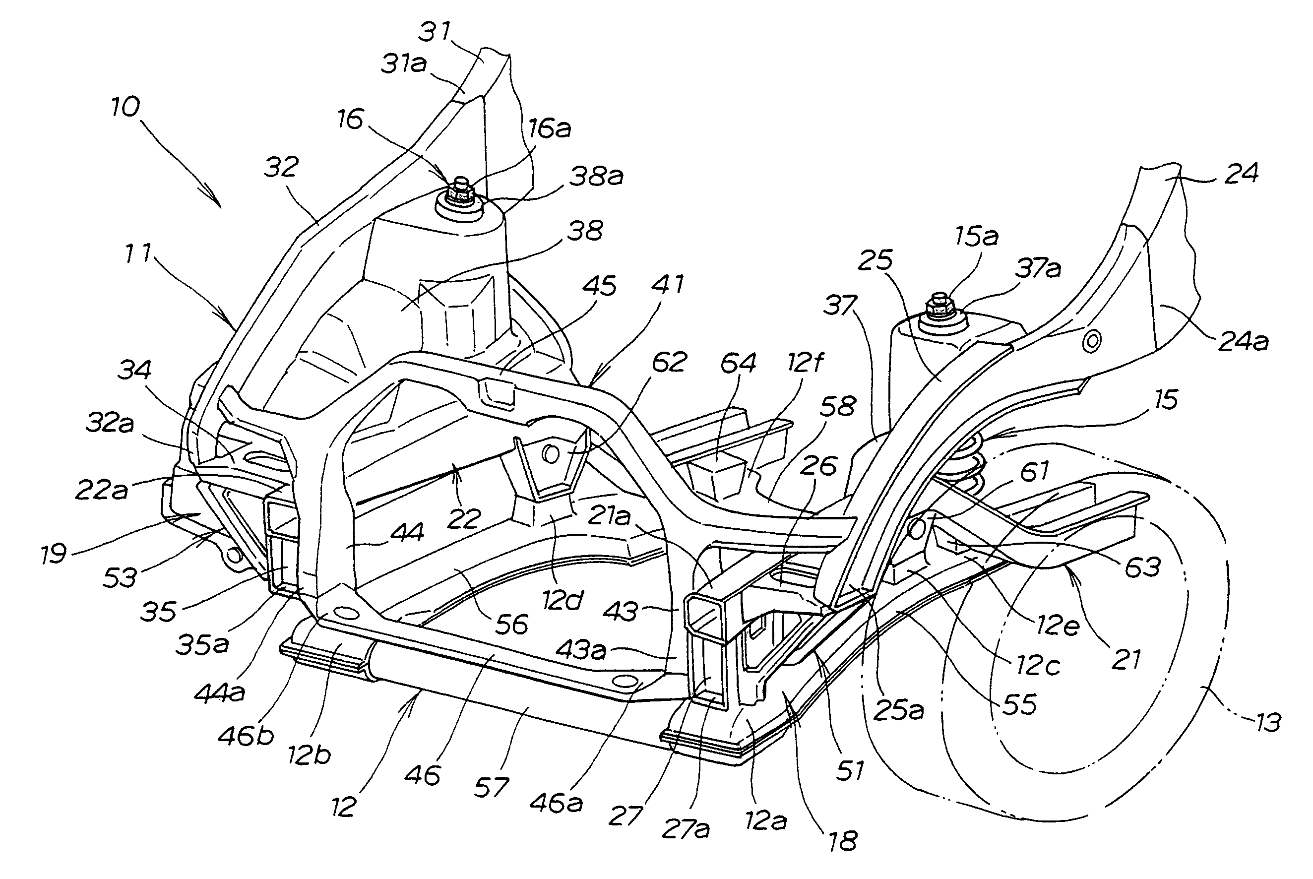
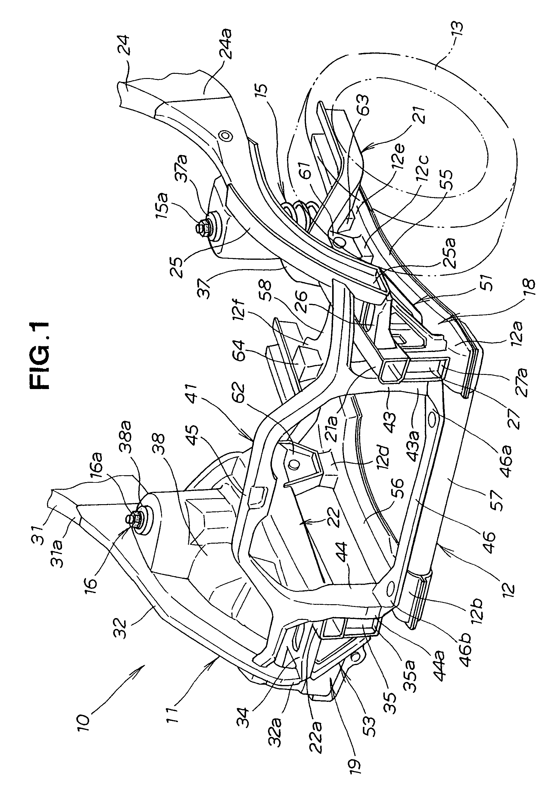
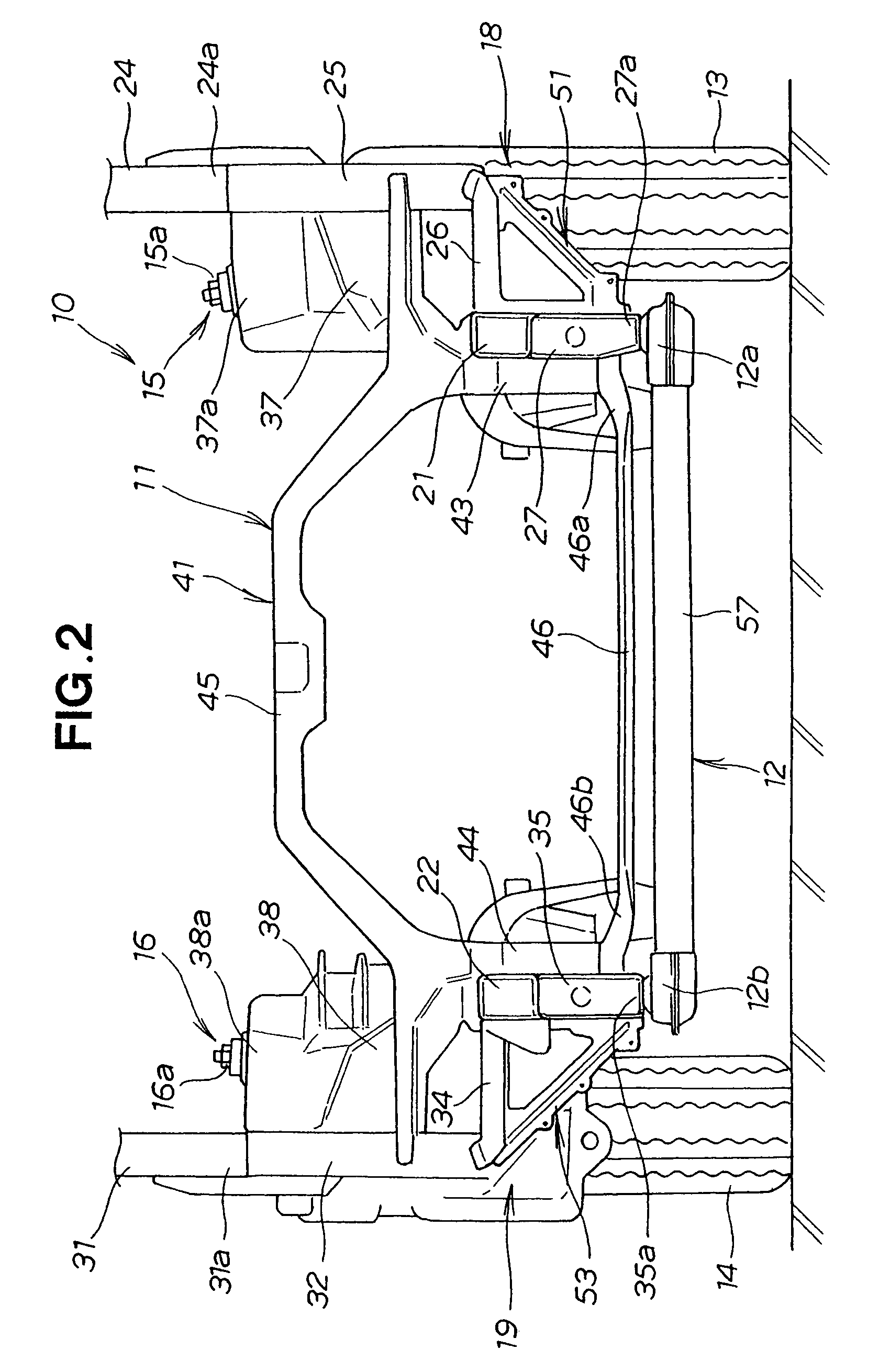
The present invention provides a vehicle front body structure that allows for effective distribution of lateral loads and reduced weight of the vehicle body. The structure includes left and right front side frames, front pillars, upper members, legs, and diagonal connecting members, which form a triangular hollow prismoidal frame section. The front body structure also includes a front bulkhead and U-shaped connecting frame, which strengthen the legs. The vehicle front body structure is lightweight and highly rigid against external forces.

Problems solved by technology

By thus using the mount space defined in each of the left and right frame sections, it is no longer necessary to provide a separate space for installation of a vehicle part component, which would lead to an increase in the size of the vehicle body.

Method used


Image

  • Vehicle front body structure
  • Vehicle front body structure
  • Vehicle front body structure

Examples


second embodiment

[0051]FIG. 9 shows the present invention in which an intercooler 111 is disposed in a mount space defined in the left frame section 18 of the vehicle front body structure. The left frame section 18 is formed in a substantially triangular hollow prismoidal configuration having a predetermined depth (see FIG. 3) in the longitudinal direction of the vehicle body. The triangular hollow prismoidal left frame section 18 includes a front diagonal brace 92 and a rear diagonal brace 96 (FIG. 3) that are spaced apart in the longitudinal direction of the vehicle body by a distance substantially equal to the depth W of the left frame section 18. The front and rear diagonal braces 92 and 96 define therebetween a mount space 101 in which the intercooler 111 is received.

[0052]The intercooler 111 has a substantially rectangular body and is connected at its upper end portion 111a with an intake hose 112 and, at its inner sidewall 111b, with a discharge hose 112. The intake hose 112 is connected to a...

third embodiment

[0055]FIG. 10 shows the present invention in which an intake duct 121 is disposed in the mount space 101 defined in the left frame section 18 of the vehicle front body structure. The intake duct 121 comprises a substantially rectangular duct body 122, an intake tube 123 for introducing outside air into the duct body 122, and a resonator 124 provided on the duct body 122. The duct body 122 is connected to the air-cleaner via a duct hose (not shown). The intake tube 123 extend upwardly from the duct body 122 through the opening 117 formed in the horizontal connecting member body 98. The duct body 122 is received in the mount space 101 defined in the left frame section 18 and mounted on a mount bracket 125. The mount bracket 125 includes an upper bracket member 125a and a lower bracket member 125b that are connected by fasteners including screws 126 to the left frame section 18 so that the intake duct 121 is immovably supported by the mount bracket 125 and the left frame section 18 in ...


PUM


Abstract

A vehicle front body structure includes left and right diagonal connecting members extending diagonally between and connecting together the lower end portions of left and right legs and the front end portions of left and right upper members. Left and right horizontal connecting members, the left and right legs and the left and right diagonal connecting members together form left and right frame sections of substantially triangular hollow prismoidal configuration having an axis extending in the longitudinal direction of the vehicle body.

Description

FIELD OF THE INVENTION[0001]The present invention relates to a vehicle front body structure for an automobile including a front side frame having a leg portion at a front end thereof and a sub-frame connected to a bottom surface of the leg portion for supporting a front suspension.BACKGROUND OF THE INVENTION[0002]Vehicle front body structures of the type concerned are known as disclosed, for example, in Japanese Patent Laid-open Publication (JP-A) No. 2005-112173. The disclosed vehicle front body structure includes a front side frame extending in a longitudinal direction of a vehicle body, a front pillar disposed upwardly and rearward of the front side frame, an upper member extending from a lower end of the front pillar in a forward direction of the vehicle body to the position located laterally outward of a front end portion of the front side frame. The upper member has a substantially rectilinear configuration and is arranged to slope upward in a rearward direction of the vehicle...

Claims


Application Information

Patent Timeline
Patent Type & Authority Patents(United States)
IPC IPC(8): B62D21/02B62D25/00B60R99/00
CPCB62D25/082
Inventor YATSUDA, EIJI
Owner HONDA MOTOR CO LTD
Learn More