
Torque-controlled rotational module

a technology of torque control and rotational module, which is applied in the field of rotational modules, can solve the problems of difficult rotation of the display, bottleneck in manufacturing and assembling the display, and complicated process of adjusting the angle of the display to a desired angle, etc., and achieve the effect of effectively limiting the rotational angle of the display and the electrical apparatus in use, the electrical apparatus, and easy rotation of the display

Inactive Publication Date: 2008-12-09
QUANTA COMPUTER INC
View PDF15 Cites 12 Cited by
  • Summary
  • Abstract
  • Description
  • Claims
  • Application Information

AI Technical Summary

Benefits of technology

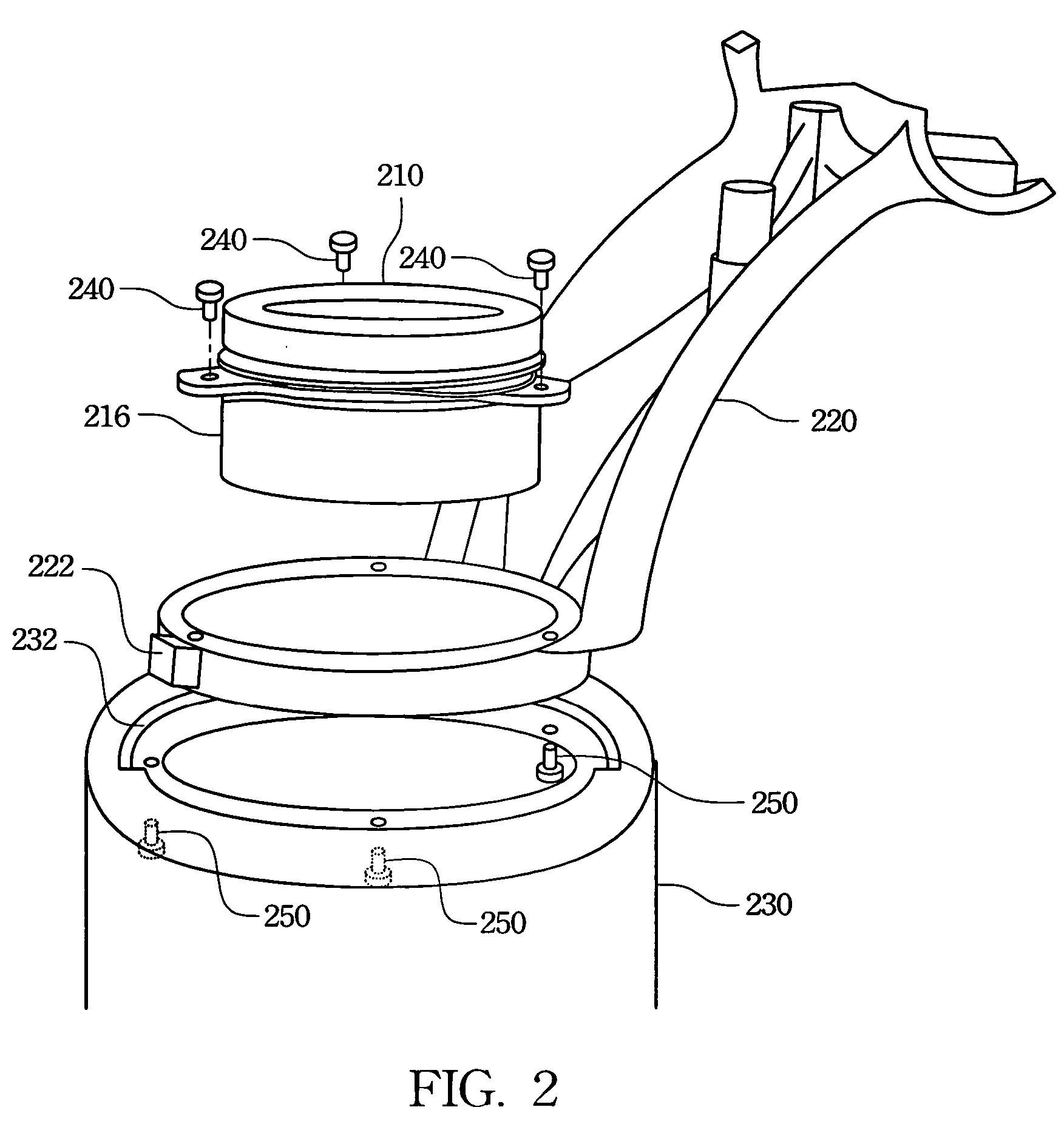
The present invention provides a torque-controlled rotational module for a display or electrical apparatus requiring a rotational function with a steady torque, and that avoids an unexpected rotation. The module includes a fixing base, rotational member, spring member, and torque adjusting ring. The module also includes wear-resisting members and arresting protrusions to avoid abrasions and rotation of the torque adjusting ring. The rotational member includes first and second fixing holes to couple to a rotational portion of the display, and the fixing base utilizes a knob and slot coupling to limit the rotational angle of the rotational member. The torque-controlled rotational module can adjust and confirm the rotational torque prior to assembly with the display or electrical apparatus, increasing the assembly quality and yield, and users can easily rotate the display and electrical apparatus with the module under the confirmed rotational torque. The module effectively limits the rotational angle of the display and electrical apparatus in use so as to increase the stability thereof.

Problems solved by technology

However, if a torque for rotating the rotational shaft is too strong, the display is difficult to rotate.
If the torque for rotating the rotational shaft is too weak, an undesired rotation of the display may occur, and may even prevent the display from being effectively fixed in the desired direction, position, and angle so as to inconvenience the user watching the images on the display.
However, a complicated process for adjusting the angle of the display to a desired angle is incurred.
However, if the torque is not correct, an operator must disassemble the rotational shaft from the display and readjust the torque of the rotational shaft.
Therefore, the conventional display shaft cannot provide a convenient assembly process for assembling the displays such that the complicated assembly process causes a bottleneck in manufacturing and assembling the displays.

Method used


Image

  • Torque-controlled rotational module
  • Torque-controlled rotational module
  • Torque-controlled rotational module

Examples


Embodiment Construction

[0021]The following description is of the best presently contemplated mode of carrying out the present invention. This description is not to be taken in a limiting sense but is made merely for the purpose of describing the general principles of the invention. The scope of the invention should be determined by referencing the appended claims.

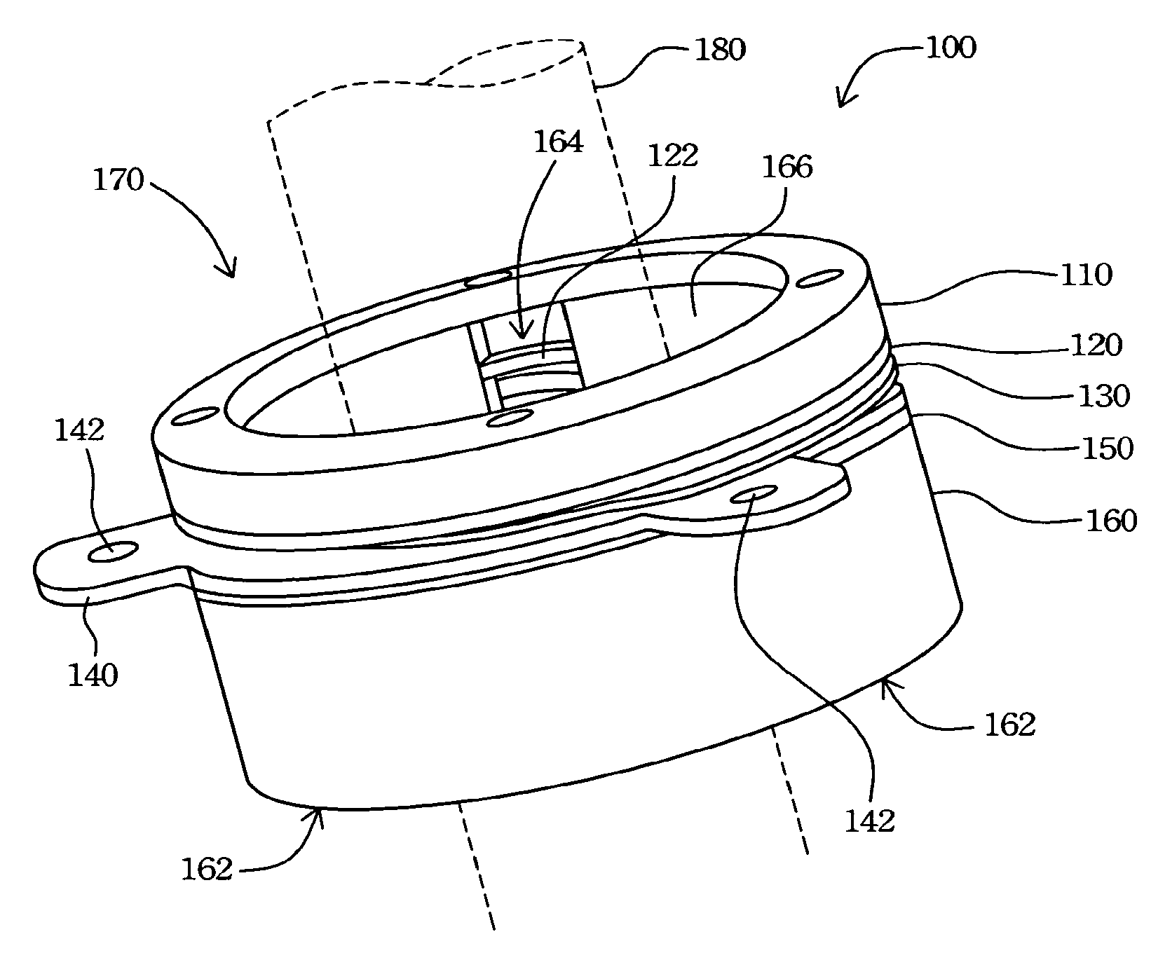
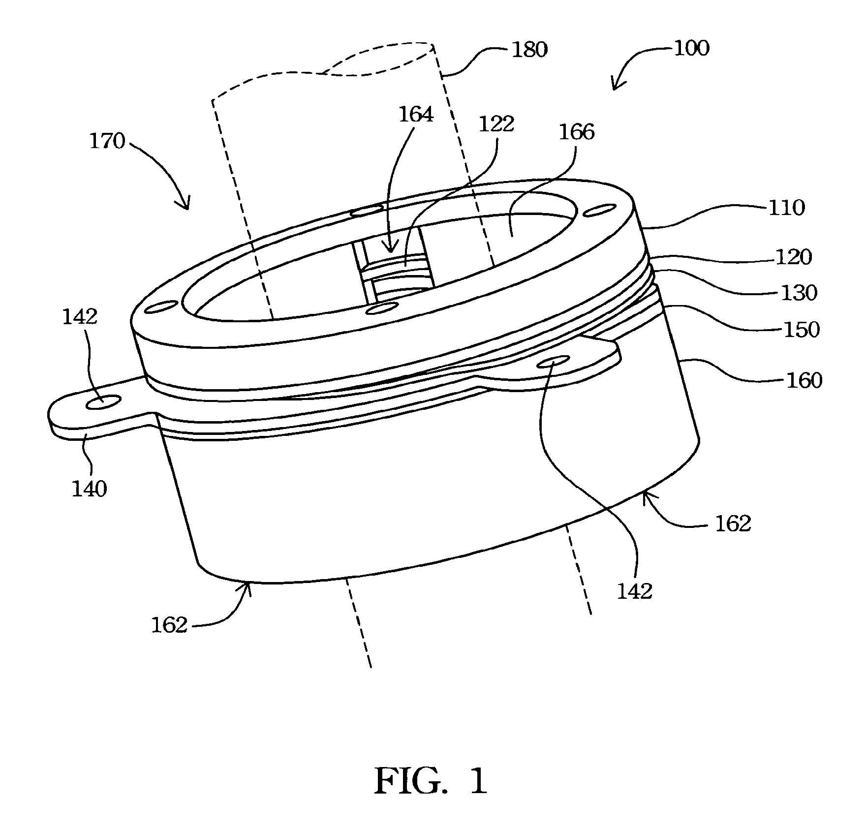
[0022]FIG. 1 is a schematic perspective view of a rotational module according to the present invention. The rotational module according to the present invention is a torque-controlled rotational module 100. The torque-controlled rotational module 100 includes a torque adjusting ring 110, a wear-resisting member 120, a spring member 130, a rotational member 140, a wear-resisting member 150, and a fixing base 160. The fixing base 160 has a fixing wall 166 and a cable hole 170. The fixing wall 166 further has a fixing indentation 164 thereon and the cable hole 170 is disposed inside the fixing wall 166.

[0023]The rotational member 140 surrounding the...


PUM


Abstract

A torque-controlled rotational module is described. The torque-controlled rotational module has a fixing base, a rotational member, a spring member, and a torque adjusting ring. The fixing base further has a fixing wall and a cable hole therein for a cable to pass therethrough. The module further utilizes wear-resisting members configured on both sides of the rotational member, between the torque adjusting ring and the fixing base, to protect the torque adjusting ring and the fixing base from wear and tear. The fixing wall further utilizes a fixing indentation to couple to arresting protrusions of the wear-resisting members to avoid rotation of the wear-resisting members. The fixing base further utilizes a knob coupled to a slot of the rotational member to limit a rotational angle of the rotational member.

Description

RELATED APPLICATIONS[0001]The present application is based on, and claims priority from, Taiwan Application Serial Number 93114820, filed May 25, 2004, the disclosure of which is hereby incorporated by reference herein in its entirety.FIELD OF THE INVENTION[0002]The present invention generally relates to a rotational module. More particular, the present invention relates to a torque-controlled rotational module.BACKGROUND OF THE INVENTION[0003]Recently, liquid crystal displays (LCD) have been widely applied in electrical products, due to the rapid progress of optical technology and semiconductor technology. Moreover, with the advantages of high image quality, compact size, light weight, low driving voltage, and low power consumption, LCDs have been introduced into portable computers, mobile phones, video cameras, personal digital assistants, desktop computer displays, multimedia televisions and various consumer electronics, and are gradually replacing the cathode ray tubes (CRT) use...

Claims


Application Information

Patent Timeline
Patent Type & Authority Patents(United States)
IPC IPC(8): E05D11/06H02N2/00
CPCF16M11/06F16M11/18H04N5/64Y10T16/551Y10T16/540345F16M2200/024
Inventor PAN, HUNG-TSAIHSU, PO-LANG
Owner QUANTA COMPUTER INC
Learn More