
Wind turbine rotor assembly and blade having acoustic flap

a technology of wind turbine blades and rotors, which is applied in the field of turbine blades, can solve the problems of inability to meet the requirements of wind turbine operation, so as to reduce the broadband and tonality of trailing edge nois

Active Publication Date: 2008-12-02
LM WIND POWER US TECH APS
View PDF19 Cites 58 Cited by
  • Summary
  • Abstract
  • Description
  • Claims
  • Application Information

AI Technical Summary

Benefits of technology

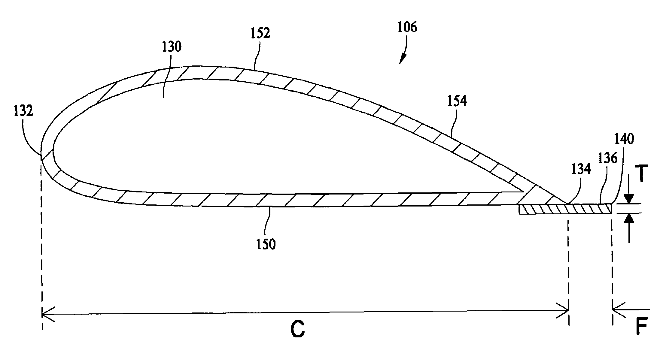
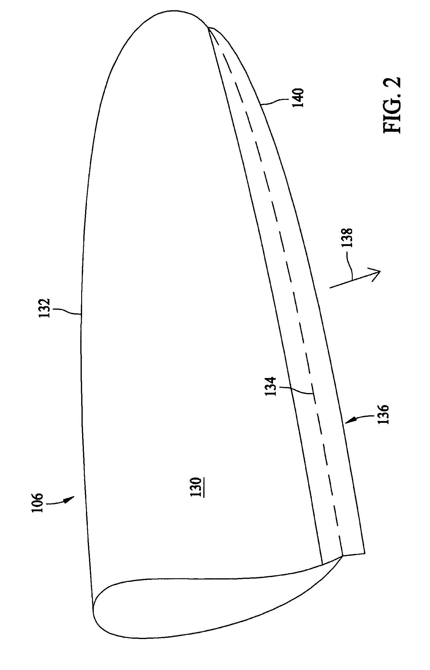
[0007]In another aspect, a rotor assembly for a wind turbine is provided. The rotor comprises a plurality of blades rotatable about an axis in response to wind impinging upon the blades. At least one of the blades includes a blade body defining a leading edge, a trailing edge and a chord distance therebetween. A rigid acoustic flap is secured to the blade body and extends outward from the trailing edge for a specified fraction of the chord distance, thereby reducing trailing edge noise broadband and tonality as the blade is rotated.
[0008]In still another aspect, a wind turbine is provided. The turbine includes a rotatable shaft coupled to a generator, and at least one blade coupled to the shaft and movable by wind for the generation of electricity. The at least one blade comprises a body defining a leading edge, a trailing edge and a chord distance therebetween. The body has a high pressure side and a low pressure side, and a rigid acoustic flap is secured to the high pressure side and extends outward from the trailing edge to a smooth distal end, thereby reducing trailing edge noise broadband and tonality.

Problems solved by technology

It has been found, however, that wind turbines can produce noise in operation that can be a nuisance in some installations.
Especially when wind turbines are placed in close relation to populated areas, aerodynamic noise emissions from the turbines in use may be unacceptable.

Method used


Image

  • Wind turbine rotor assembly and blade having acoustic flap
  • Wind turbine rotor assembly and blade having acoustic flap
  • Wind turbine rotor assembly and blade having acoustic flap

Examples


Embodiment Construction

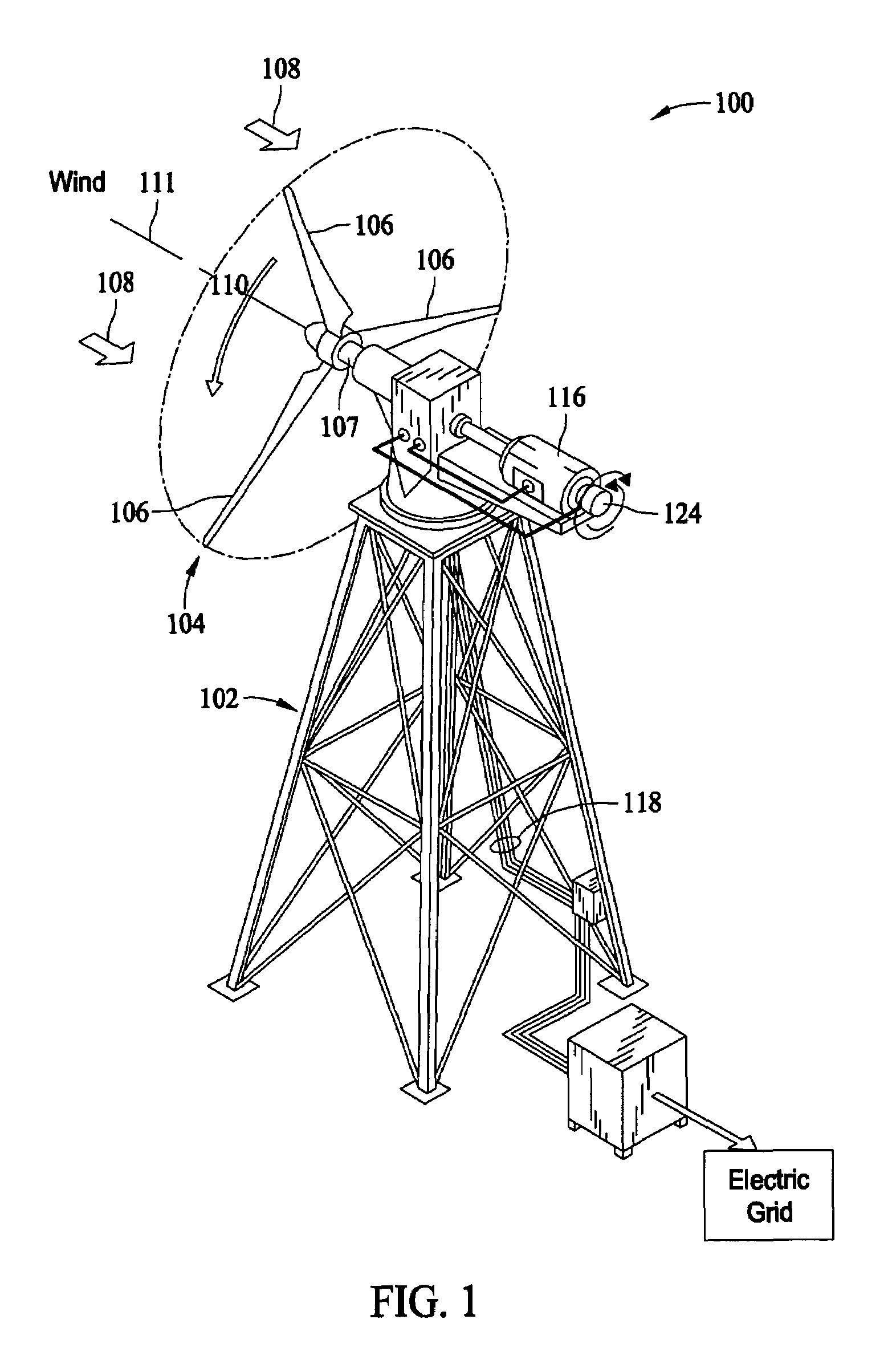
[0012]FIG. 1 is a perspective view of an exemplary embodiment of a wind turbine 100. In one embodiment, the wind turbine 100 mounted on a pedestal 102, and a rotor assembly 104 is mounted to the upper portion of the pedestal 102. The rotor assembly 104 has one or more blades 106 connected to a shaft 107. When wind blows, for example from the direction 108, the blades 106 and the shaft 107 rotate in the direction of arrow 110 about an axis 111 in response to wind impinging upon the blades 106. However, in other embodiments, the rotational direction may be in the opposite direction from the direction of arrow 110 with an equivalent but opposite effect. Furthermore, other wind turbine configurations, such as vertical axis wind turbine configurations, may be used with equal utility.

[0013]The wind, acting on the blades 106, supplies a torque to the shaft 107 in the rotational direction 110 and the amount of supplied torque is a function of the wind speed and rotor speed. The rotating sha...


PUM


Abstract

A wind turbine includes a rotor assembly having at least one blade with a blade body defining a leading edge and a trailing edge and adapted for movement in response to a wind flow over the body to produce electricity. A rigid acoustic flap extends outward from the trailing edge, and a distal end of the acoustic flap is substantially smooth and continuous. The flap reduces acoustic noise generated by the blade in use.

Description

BACKGROUND OF THE INVENTION[0001]This invention relates generally to turbines, and more particularly, to turbine blades for wind turbines.[0002]Generation of electricity by wind or water power without using fossil fuels is desirable to produce electrical power in a more environmentally friendly manner. Wind turbines are known that convert rotational movement of turbine blades to electricity as wind causes the blades to rotate.[0003]It has been found, however, that wind turbines can produce noise in operation that can be a nuisance in some installations. Especially when wind turbines are placed in close relation to populated areas, aerodynamic noise emissions from the turbines in use may be unacceptable.[0004]A variety of efforts have been made to reduce aerodynamic noise of turbine blades in use. For example, U.S. Pat. No. 6,830,436 describes a serrated rear member that is attachable to a main blade body to reduce noise. U.S. Pat. No. 6,729,846 describes turbine blades having a roug...

Claims


Application Information

Patent Timeline
Patent Type & Authority Patents(United States)
IPC IPC(8): F03D11/00
CPCF03D1/0633F03D1/0675Y02E10/721F05B2260/96Y02E10/72
Inventor HERR, STEFAN
Owner LM WIND POWER US TECH APS
Learn More