Representation of whirl in fixed cutter drill bits
a technology of fixed cutter and drill bit, which is applied in the direction of instruments, cad techniques, analogue processes for specific applications, etc., can solve the problem that the bit may not be suitable for drilling a borehole, and achieve the effect of improving the selection of the bi
- Summary
- Abstract
- Description
- Claims
- Application Information
AI Technical Summary
Benefits of technology
Problems solved by technology
Method used
Image
Examples
Embodiment Construction
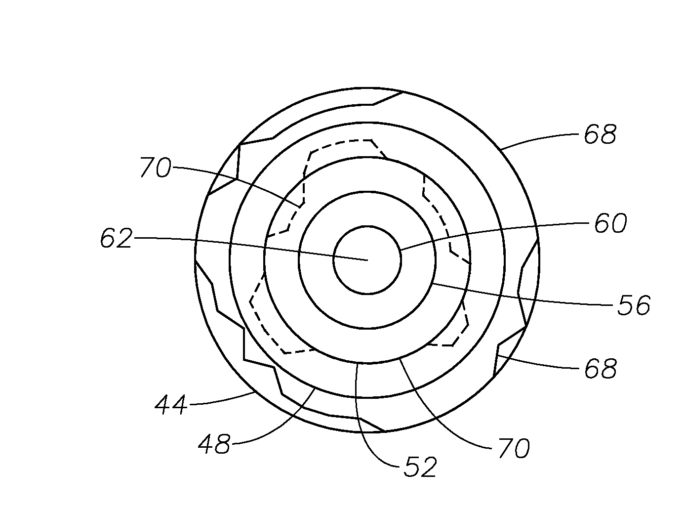
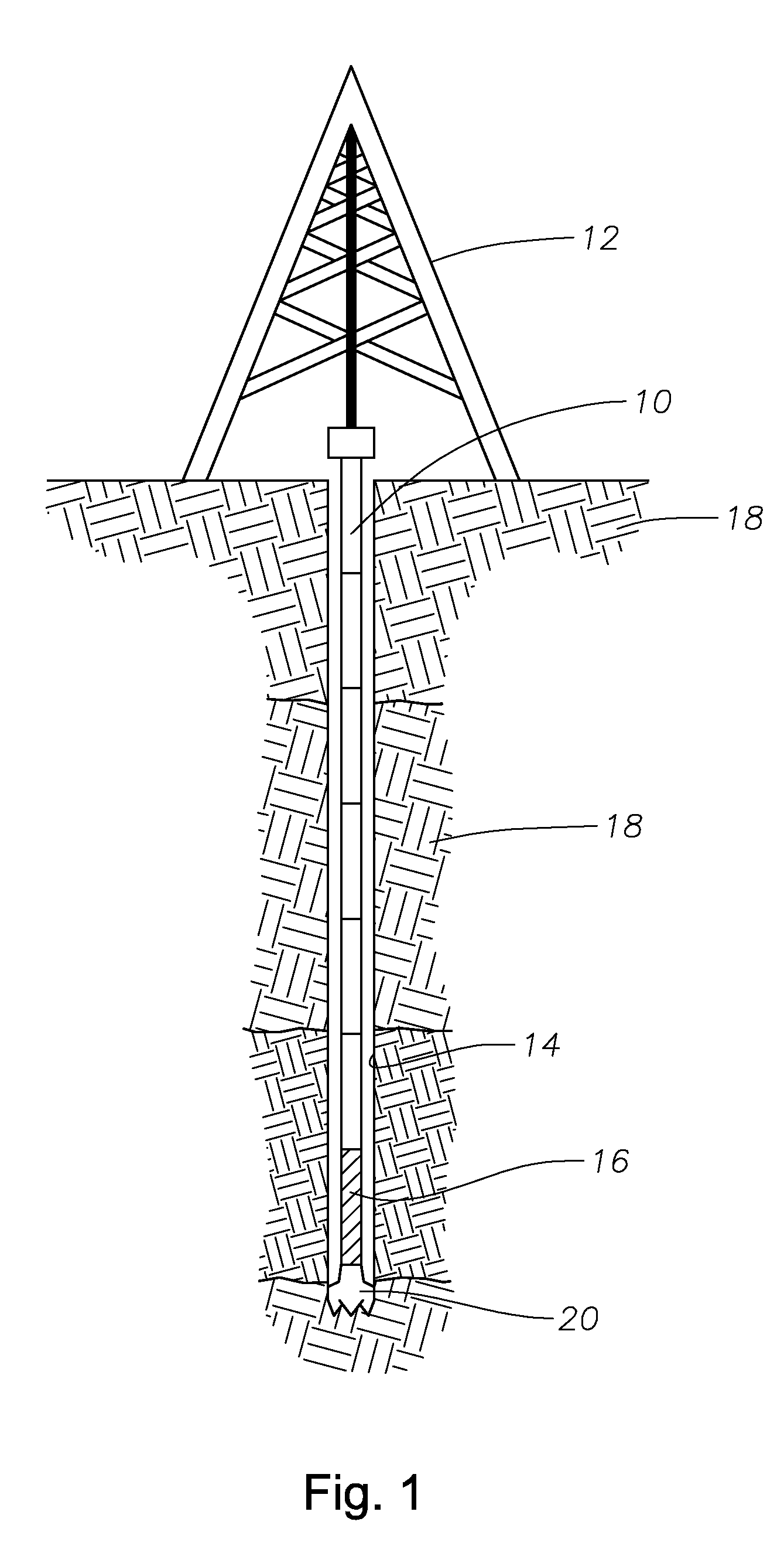
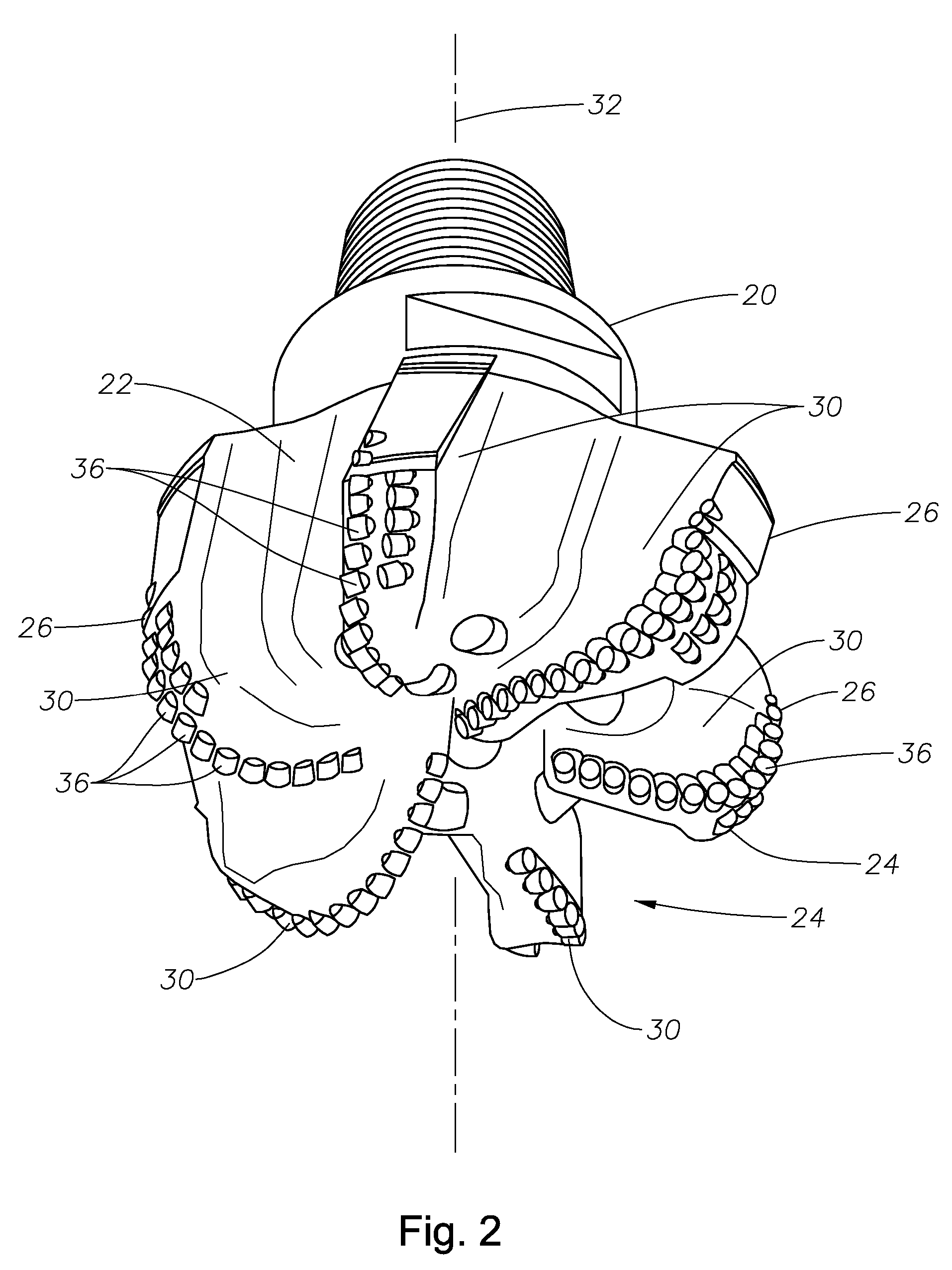
[0022]FIG. 1 shows a drill string 10 suspended by a derrick 12 for drilling a borehole 14 into the earth 18 for minerals exploration and recovery, particularly petroleum and natural gas. A bottom-hole assembly (BHA) 16 is located in the drill string 10 at the bottom of the borehole 14. The BHA 16 includes a fixed cutter drill bit 20 (shown in more detail in FIGS. 2 and 3) having a bit body 22, a leading face 24, and a gauge region 26. The drill bit 20 is caused to rotate downhole as it penetrates into the earth allowing the drill string 10 to advance, forming the borehole 14.
[0023]The fixed cutter drill bit 20 is designed with predictable stability, that is, the bit is designed such that its tendency to ‘whirl’ is predicted in advance so that its properties in operation can be matched to the drilling requirements. Although it is generally believed that the less ‘whirl’ a bit has, the better, there are circumstances where there is a trade off between ‘whirl’ tendency and drilling rat...
PUM
 Abstract
Description
Claims
Application Information
 - R&D
- Intellectual Property
- Life Sciences
- Materials
- Tech Scout
- Unparalleled Data Quality
- Higher Quality Content
- 60% Fewer Hallucinations
Browse by: Latest US Patents, China's latest patents, Technical Efficacy Thesaurus, Application Domain, Technology Topic, Popular Technical Reports.
© 2025 PatSnap. All rights reserved.Legal|Privacy policy|Modern Slavery Act Transparency Statement|Sitemap|About US| Contact US: help@patsnap.com


