
Color edge based system and method for determination of 3D surface topology

a 3d object and topology technology, applied in the field of 3d scanning of the surface of a 3d object, can solve the problems of inconvenient and time-consuming processes, no reliable way to distinguish, and the coordinates of the points positioned on this line will be obtained

Inactive Publication Date: 2008-11-25
C M D CONTROLLED MICRO DEVICES +1
View PDF17 Cites 41 Cited by
  • Summary
  • Abstract
  • Description
  • Claims
  • Application Information

AI Technical Summary

Benefits of technology

"The present invention provides a simple and reliable method for generating a 3D model of a colored surface of a 3D object using a unique colored pattern. The method utilizes a unique colored pattern that is projected onto the surface of the object and then an image grabbing apparatus captures the reflected image of the colored pattern. The method utilizes color jumps, which are abrupt color changes between adjacent strips, to easily identify the color edges and accurately calibrate the object. The colored strips form an angle with respect to contour or silhouette lines on the surface of the object, which ensures optimal identification of points on the object. The method also includes a first step of calibration that includes using a 2D calibration grid and calculating a set of coefficients to obtain the {X,Y,Z} coordinates of the calibration points. The method is advantageous over conventional techniques as it reduces the intrinsic ambiguity of using color lines and enhances the calibration process."

Problems solved by technology

There is a well known ambiguity problem associated with the simultaneous projection of several lines onto the surface of the object, i.e., there is no reliable way to distinguish between different white lines of the 2D image in the presence of noise, because some points could be missed and other points could be falsely assigned to the wrong line.
However, the problem with the aforesaid ‘one white-line technique’ is that only the coordinates of the points positioned on this line will be obtained.
Both solutions are very long, inconvenient and time consuming processes and they require complicated hardware or mechanical tools.
However, according to Fitracks, the number of the lines is limited to eight and, in any case, can not be significantly increased, thus restricting 3D resolution of Fitrack's scanner.
In addition, Fitracks utilizes laser light, which is unacceptable in applications where the tested object is a human face.
However, the problem with the latter approach is that it can only be applied for white or homogeneously colored (say grey, yellow or green) colored objects, because when projected on a colored object, such as a human face, one or more of the colored lines could be similar to the colors in the object, which would render the color recognition technique unreliable.
However, using one camera as disclosed by U.S. Pat. No. 6,028,672, requires utilization of several mirrors and a LCD shutter, which makes the disclosed system expensive.
However, a problem with this method is that, the spectrum of the light reflected from the object under test, is dictated according to the absorption spectrum of the reflecting surface, and, even worse, according to the reflection angle and texture of the reflecting surface.
However, this system can not be applied to human face, because most of the markers will not be reliably visible by the camera, or reliably resolved.
However, the aforesaid method / apparatus utilize a phase detection algorithm, which is incapable of handling missing sections in the lines.
However, these solutions employ rather complex mathematical algorithms which are mostly highly unreliable in the real life environment, and / or use laser and / or digital projectors, which is a drawback by itself because of the cost.
All of the above-mentioned solutions have not provided a satisfactory solution to the problem of obtaining a 3D scanning of an object by means of very low cost, compactly designed, and reliable 3D scanning apparatus.

Method used


Image

  • Color edge based system and method for determination of 3D surface topology
  • Color edge based system and method for determination of 3D surface topology
  • Color edge based system and method for determination of 3D surface topology

Examples


Embodiment Construction

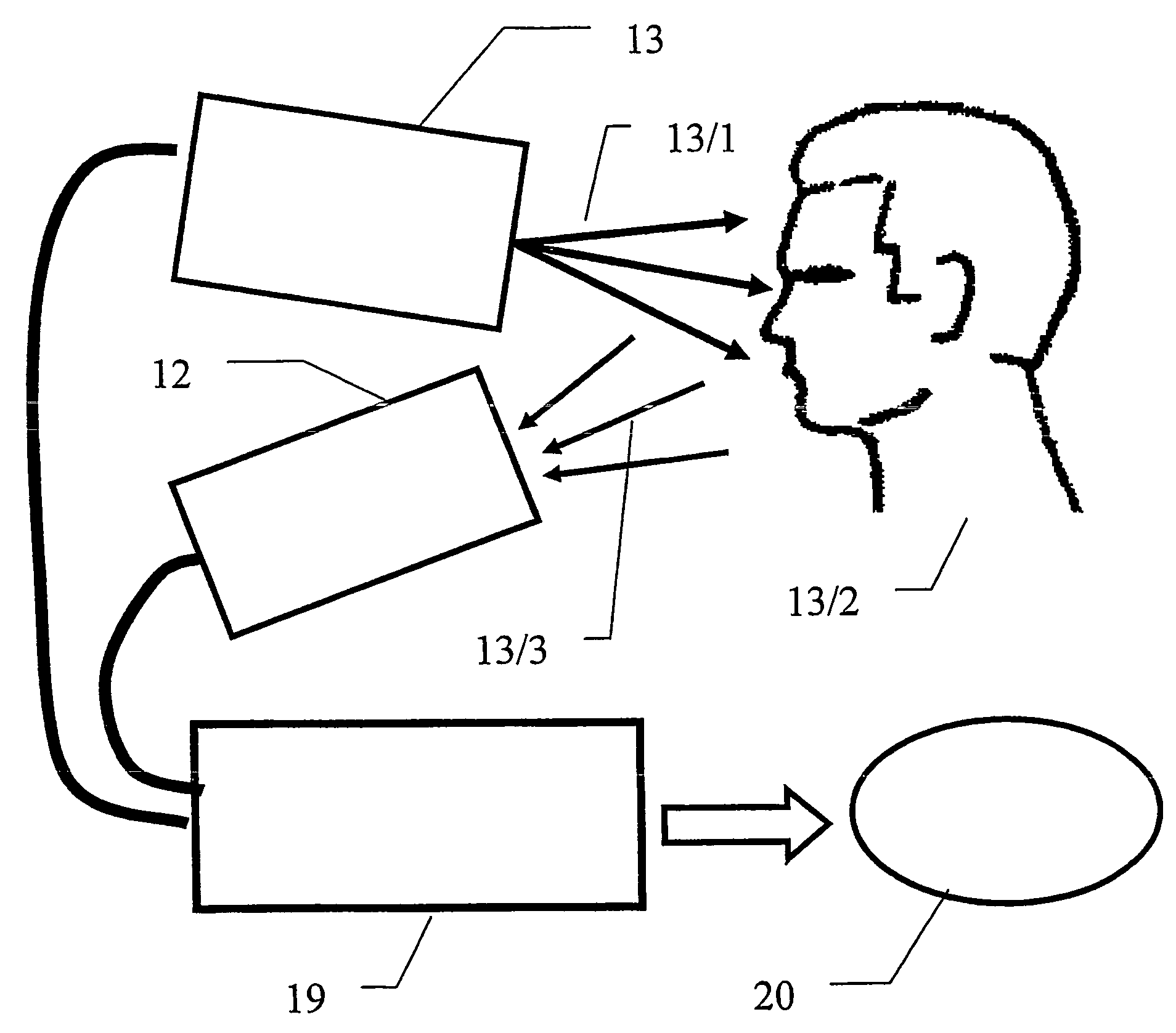
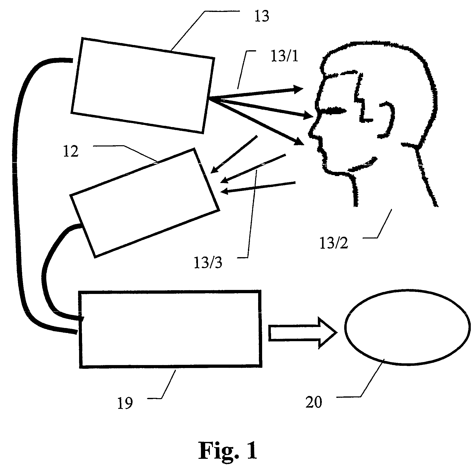
[0157]FIG. 1 schematically illustrates a general layout and functionality of the present invention. Slide projector 13 irradiates a color edge pattern (the radiation being schematically indicated as 13 / 1) onto a face 13 / 2 of a person. A portion 13 / 3 of the irradiated color light 13 / 1 is reflected from face 13 / 2, and received by an image grabbing apparatus 12, which could be; e.g., a digital video, or still, camera. The grabbed image is forwarded to computer 19, which includes corresponding software for processing the acquired image, for obtaining a 3D True Color Model 20, or 3D representation, of the human face 13 / 2. The 3D True Color Model of the human face relates to points that were derived from a set of points positioned on the surface of the human face, each point being characterized by its {X,Y,Z} coordinates and by its true color attributes. This 3D Model can be used by the software to generate 2D projections, or images, of the human face from different angles and positions.

[...


PUM


Abstract

A method and system for determining surface topology of a three-dimensional (3D) structure, based on a structured pattern that is projected onto the surface structure, and images of the pattern superposed on the structured surface are analysed to provide surface coordinates of the structure. The pattern comprises a plurality of unique color edges defined between pairs of differently-colored stripes, which substantially overcomes ambiguity problems. In one embodiment, a calibration method is provided enabling the surface coordinates to be obtained from a single image of the structure.

Description

FIELD OF THE INVENTION[0001]The present invention relates to the field of 3-dimensional (3D) scanning of a surface of a 3D object. More particularly, the present invention relates to a method for reliably, but yet in a simple manner, generating 3D coordinates of a surface of a 3D object, for example 3D coordinates of a surface of a human face.BACKGROUND OF THE INVENTION[0002]One possible way of obtaining 3D coordinates of an 3D object by from 2D digital image is carried out by utilizing, what is commonly known as the Original “Structured Light Technique”, which is usually based on irradiating (i.e., projecting, e.g., white line(s), or strip(s), onto the surface of a 3D object, employing corresponding 2D image processing technique for distinguishing these lines / strips from other portions of the object (i.e., by usually utilizing simple threshold techniques), after which a known triangulation algorithm is utilized for calculating the 3D coordinates of points residing on these lines / st...

Claims


Application Information

Patent Timeline
Patent Type & Authority Patents(United States)
IPC IPC(8): G09G5/02G06T15/00G02BG06TG09G5/00
CPCG01B11/2509
Inventor KOSOLAPOV, SAMUEL
Owner C M D CONTROLLED MICRO DEVICES
Learn More