Fire suppression and indicator system and fire detection device
a technology of indicator system and fire detection device, which is applied in the direction of fire alarm radiation actuation, fire alarms, instruments, etc., can solve the problems of flammable materials posing a serious threat to the freight transporter, the freight transporter, and the freight transporter, and the danger of fire is just as grea
- Summary
- Abstract
- Description
- Claims
- Application Information
AI Technical Summary
Benefits of technology
Problems solved by technology
Method used
Image
Examples
first embodiment
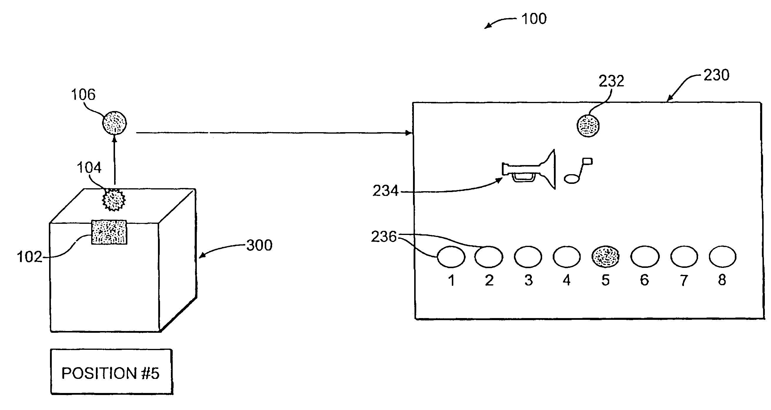
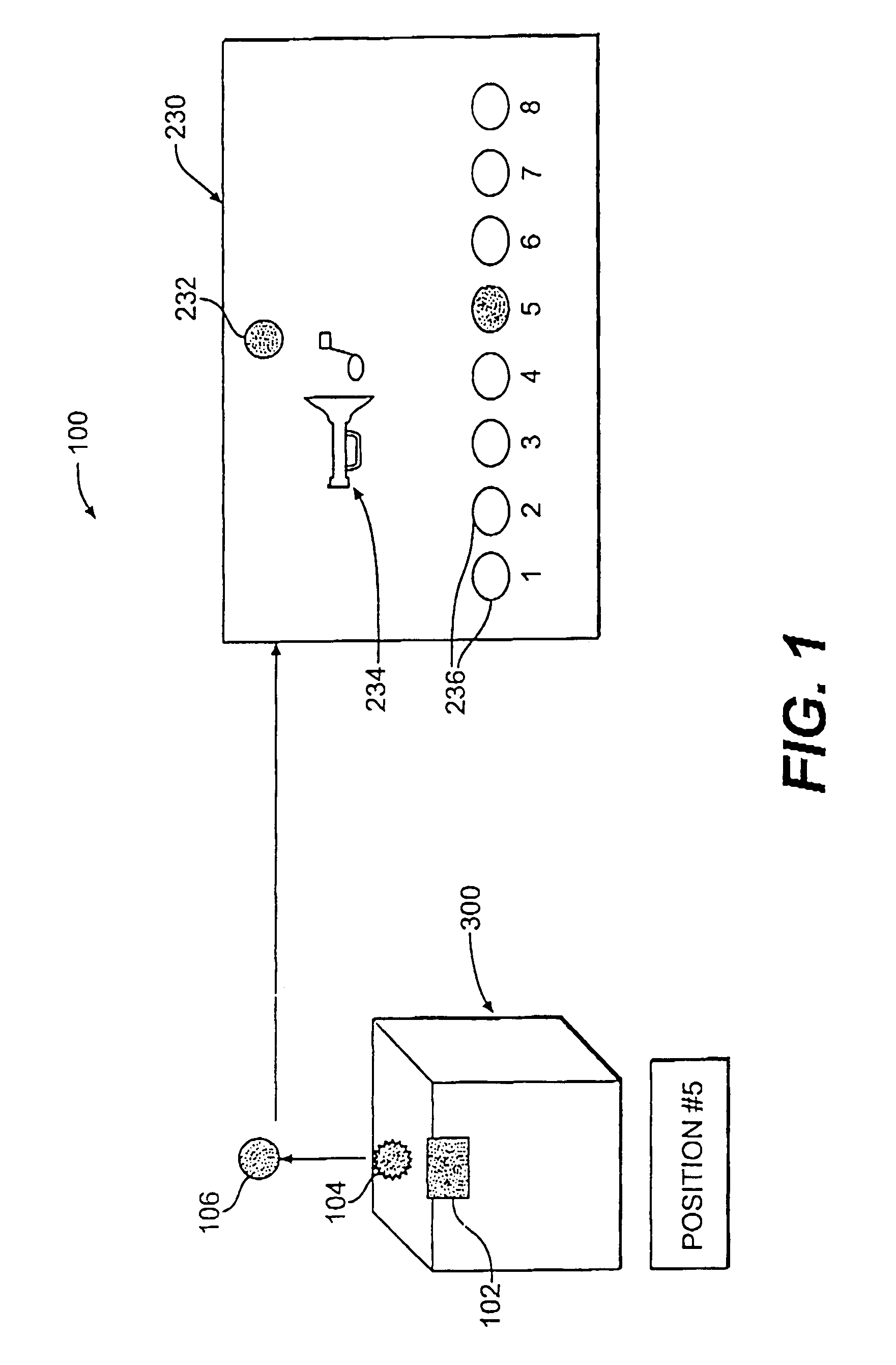
[0025]FIG. 1 is a schematic representation of a fire suppression and indication system;
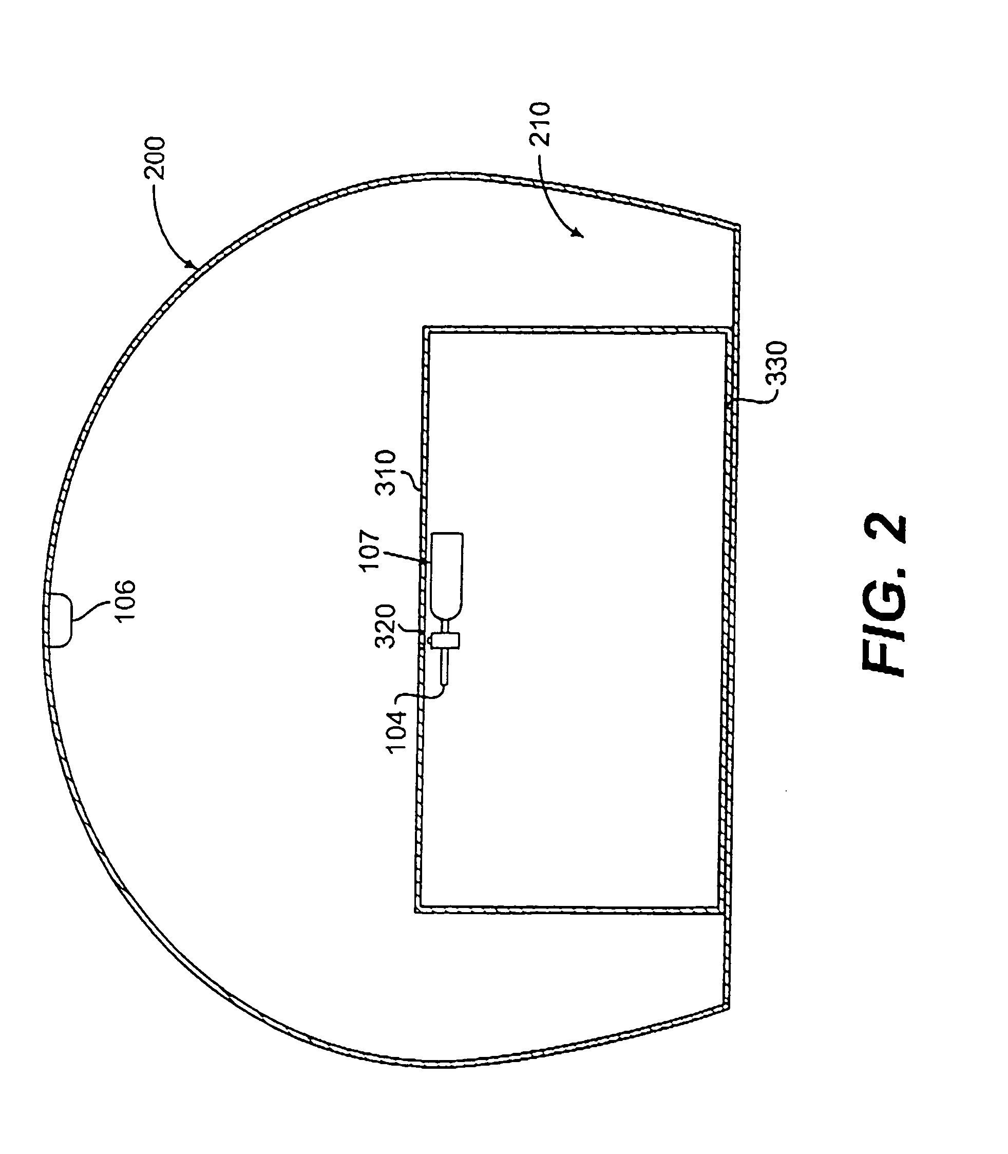
[0026]FIG. 2 is one possible arrangement of the fire suppression and indication system of FIG. 1 in an aircraft;
[0027]FIG. 3 is a schematic of the IR transmitter of the fire suppression and indication system of FIG. 1;
[0028]FIG. 4 is one embodiment of the fire detection and suppression device of FIG. 1;
[0029]FIG. 5 is an exploded perspective view of the device and transmitter of FIG. 4;
[0030]FIGS. 6A and 6B are cross-sectional views taken along the line VI-VI of FIG. 4, where
[0031]FIG. 6A is prior to discharge and
[0032]FIG. 6B is during discharge;
[0033]FIG. 7 is another embodiment of the fire detection and suppression device;
[0034]FIG. 8 is an exploded perspective view of the device and transmitter of FIG. 7;
[0035]FIGS. 9A and 9B are cross-sectional views taken along the line IX-IX of FIG. 7, where
[0036]FIG. 9A is prior to discharge and
[0037]FIG. 9B is during discharge;
[0038]FIG. 10 is a cross-sec...
second embodiment
[0039]FIG. 11 is the fire suppression and indication system of the present invention;
[0040]FIG. 12 is a schematic of the fire suppression and indication system;
[0041]FIG. 13 is a perspective view of the floor system and storage units arranged in the cargo area of the aircraft;
[0042]FIGS. 14A and 14B are cross-sectional views of a pop-up valve in the fire suppression and indication system of FIG. 11, where 14A is prior to discharge and 14B is during discharge;
[0043]FIG. 15. is a exploded view of the pop-up valve of FIG. 11; and
[0044]FIG. 16 is a schematic of the transmitter for the second embodiment of FIG. 11.
PUM
 Abstract
Description
Claims
Application Information
 - R&D
- Intellectual Property
- Life Sciences
- Materials
- Tech Scout
- Unparalleled Data Quality
- Higher Quality Content
- 60% Fewer Hallucinations
Browse by: Latest US Patents, China's latest patents, Technical Efficacy Thesaurus, Application Domain, Technology Topic, Popular Technical Reports.
© 2025 PatSnap. All rights reserved.Legal|Privacy policy|Modern Slavery Act Transparency Statement|Sitemap|About US| Contact US: help@patsnap.com


