
Identification of the channel frequency response using chirps and stepped frequencies

a frequency response and channel technology, applied in the field of telemetry systems, can solve the problems of affecting baseband signaling, not being free of noise sources, and the system to support this is quite complex,

Active Publication Date: 2008-11-18
BAKER HUGHES HLDG LLC
View PDF16 Cites 18 Cited by
  • Summary
  • Abstract
  • Description
  • Claims
  • Application Information

AI Technical Summary

Problems solved by technology

The system to support this is quite complex, with both downhole and surface components that operate in step.
Baseband signaling is affected by torque noise and the stick-slip behavior of the drillstring.
The passband frequency bandwidth, however, is also not free of noise sources: for example, pump noise can play a major role in distorting the signal.
In passband filtering, one of the central issues is the selection of frequencies at which the signal is to be transmitted.
The problem is that of harmonic distortion wherein the mechanical vibrator generates one or more harmonics of the fundamental frequencies.
In the presence of harmonics, the processed signal may be severely affected by harmonic distortion.
The generation of multiple sweeps is time-consuming and the phase encoding adds to the complexity of the system.
The problem also occurs in cross-well tomography where swept frequency sources are used.

Method used


Image

  • Identification of the channel frequency response using chirps and stepped frequencies
  • Identification of the channel frequency response using chirps and stepped frequencies
  • Identification of the channel frequency response using chirps and stepped frequencies

Examples


Embodiment Construction

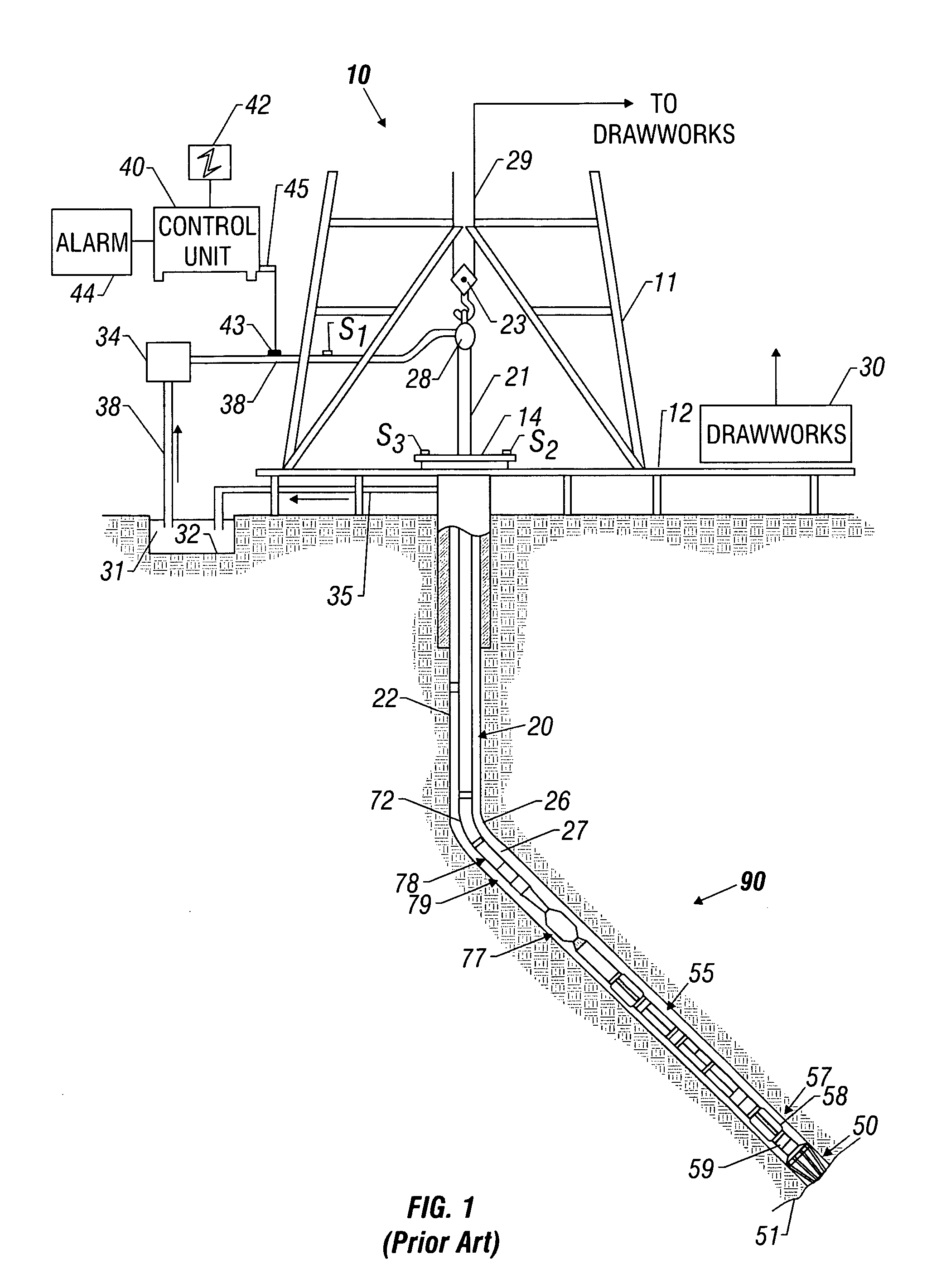
[0032]FIG. 1 shows a schematic diagram of a drilling system 10 with a drillstring 20 carrying a drilling assembly 90 (also referred to as the bottom hole assembly, or “BHA”) conveyed in a “wellbore” or “borehole”26 for drilling the wellbore. The drilling system 10 includes a conventional derrick 11 erected on a floor 12 which supports a rotary table 14 that is rotated by a prime mover such as an electric motor (not shown) at a desired rotational speed. The drillstring 20 includes a tubing such as a drill pipe 22 or a coiled-tubing extending downward from the surface into the borehole 26. The drillstring 20 is pushed into the wellbore 26 when a drill pipe 22 is used as the tubing. For coiled-tubing applications, a tubing injector, such as an injector (not shown), however, is used to move the tubing from a source thereof, such as a reel (not shown), to the wellbore 26. The drill bit 50 attached to the end of the drillstring breaks up the geological formations when it is rotated to dri...


PUM


Abstract

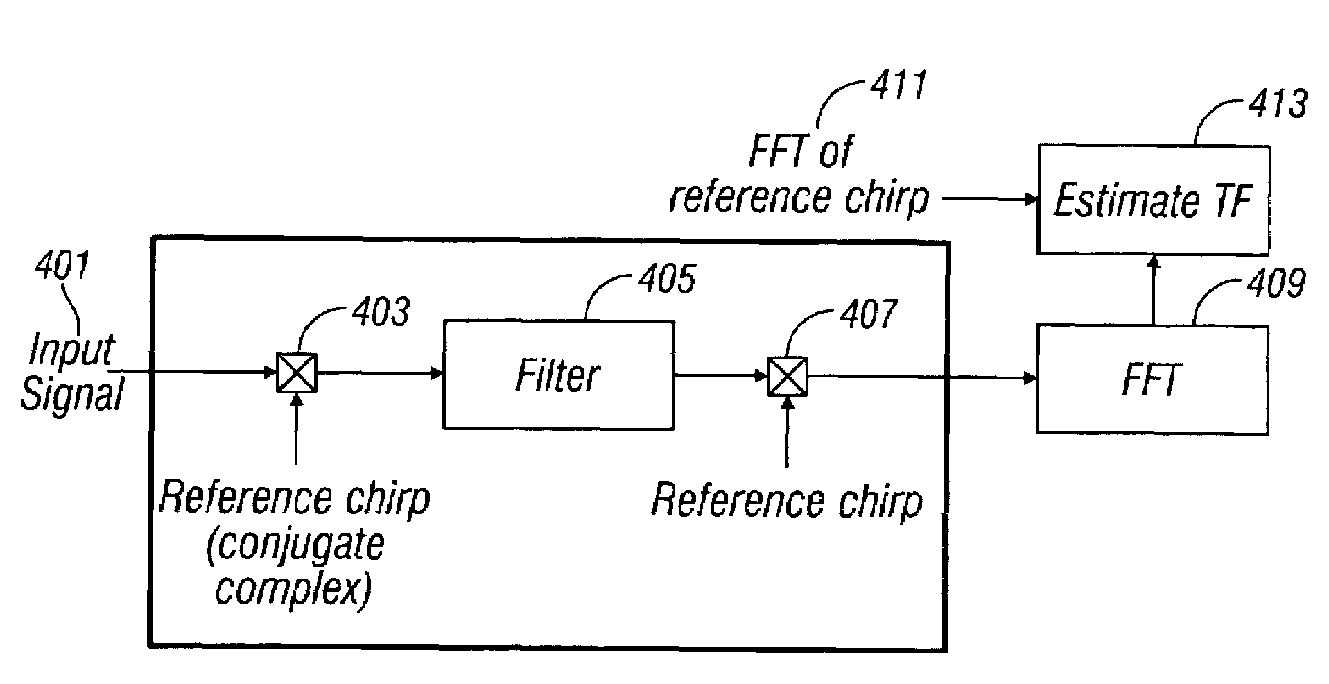
The transfer function of the communication channel in a mud pulse telemetry system is determined by sending a known signal through the channel and spectral analysis of the received signal. The known signal may be a chirp signal or a stepped frequency signal. Based on the determined transfer function, operating parameters of the pulser are adjusted.

Description

CROSS-REFERENCES TO RELATED APPLICATIONS[0001]This application claims priority from U.S. Provisional Patent Application Ser. No. 60 / 629,990 filed on 22 Nov. 2004 and U.S. Provisional Patent Application Ser. No. 60 / 631,439 filed on 29 Nov. 2004.BACKGROUND OF THE INVENTION[0002]1. Field of the Invention[0003]The present invention relates to telemetry systems for communicating information from a downhole location to a surface location, and, more particularly, to a method of determining channel characteristics of a mechanical telemetry system such as a mud pulse telemetry system. The term “mechanical” as used herein relates to telemetry governed by, or in accordance with the principles of mechanics, including acoustics and fluid mechanics.[0004]2. Description of the Related Art[0005]Drilling fluid telemetry systems, generally referred to as mud pulse systems, are particularly adapted for telemetry of information from the bottom of a borehole to the surface of the earth during oil well d...

Claims


Application Information

Patent Timeline
Patent Type & Authority Patents(United States)
IPC IPC(8): G01V1/00H04H60/31
CPCE21B47/18G01H15/00G01V1/003G01V11/002
Inventor HENTATI, NABILRECKMANN, HANNOWASSERMANN, INGOLF
Owner BAKER HUGHES HLDG LLC
Learn More