Device for protection of the bearing of an electrical machine against damaging passage of current

a technology for electrical machines and bearings, applied in the field of bearings, can solve the problems of relatively high associated cost, spark erosion, and bearing damage, and achieve the effect of preventing the passage of curren

Active Publication Date: 2008-11-04
AB SKF
View PDF15 Cites 3 Cited by
  • Summary
  • Abstract
  • Description
  • Claims
  • Application Information

AI Technical Summary

Benefits of technology

[0002]This invention generally relates to bearings. More particularly, the invention pertains to a device for protecting the bearing of an electrical machine against the passage of current.
[0006]A device that protects the bearing of an electrical machine against current passage comprises a compensation circuit which produces a compensation current which compensates for a parasitic current arising during operation of the electrical machine and passing through the bearing and a coupling element for direct or indirect coupling of the compensation current into the bearing.
[0005]In this regard, the technical article “High Frequency Leakage Current Reduction Based on a Common-Mode Voltage Compensation Circuit” in the IEEE journal, 1996, pages 1961-1967, describes compensating high frequency leakage currents using a compensation circuit. The wiring is designed such that compensation occurs in the power path, i.e. upstream of the connected load. This has the disadvantage that the compensation circuit is incorporated into the power circuit and thus its components must be designed for comparatively high wattages. Moreover any reactive component which has been inserted into the power circuit, such as for example an inductance, a capacitance or a filter, increases the number of resonant frequencies, for which, when excited, unpredictable overvoltages can occur. Since, when using a frequency converter, it can be largely assumed that all these resonant frequencies can be excited, there is a high risk that such an overvoltage will occur.
[0007]According to another aspect of the invention, a device for protecting a bearing, which supports a rotor of an electrical machine, from passage of parasitic current arising from operation of the electrical machine comprises means for producing compensation current corresponding in magnitude to the parasitic current but opposite in phase to the parasitic current, and coupling means for coupling the compensation current into the bearing.

Problems solved by technology

In electrical machinery, for example electric motors which are pivotally supported by a bearing, there is the danger that current will flow through the bearing and that the associated spark erosion will lead to bearing damage.
The associated current flows ultimately cause voltage to form on the bearing, which voltage can be greater than the breakdown strength of the lubricating film in the bearing and thus can trigger spark erosion.
This can have a relatively high associated cost, however, depending on the special circumstances of the application.
Moreover, DC electrical insulation of the bearing does not always constitute sufficient protection.
Thus, for example, for high frequency parasitic currents there is the danger that coupling into the bearing will take place capacitively.
This has the disadvantage that the compensation circuit is incorporated into the power circuit and thus its components must be designed for comparatively high wattages.
Moreover any reactive component which has been inserted into the power circuit, such as for example an inductance, a capacitance or a filter, increases the number of resonant frequencies, for which, when excited, unpredictable overvoltages can occur.
Since, when using a frequency converter, it can be largely assumed that all these resonant frequencies can be excited, there is a high risk that such an overvoltage will occur.

Method used


Image

  • Device for protection of the bearing of an electrical machine against damaging passage of current
  • Device for protection of the bearing of an electrical machine against damaging passage of current

Examples


Embodiment Construction

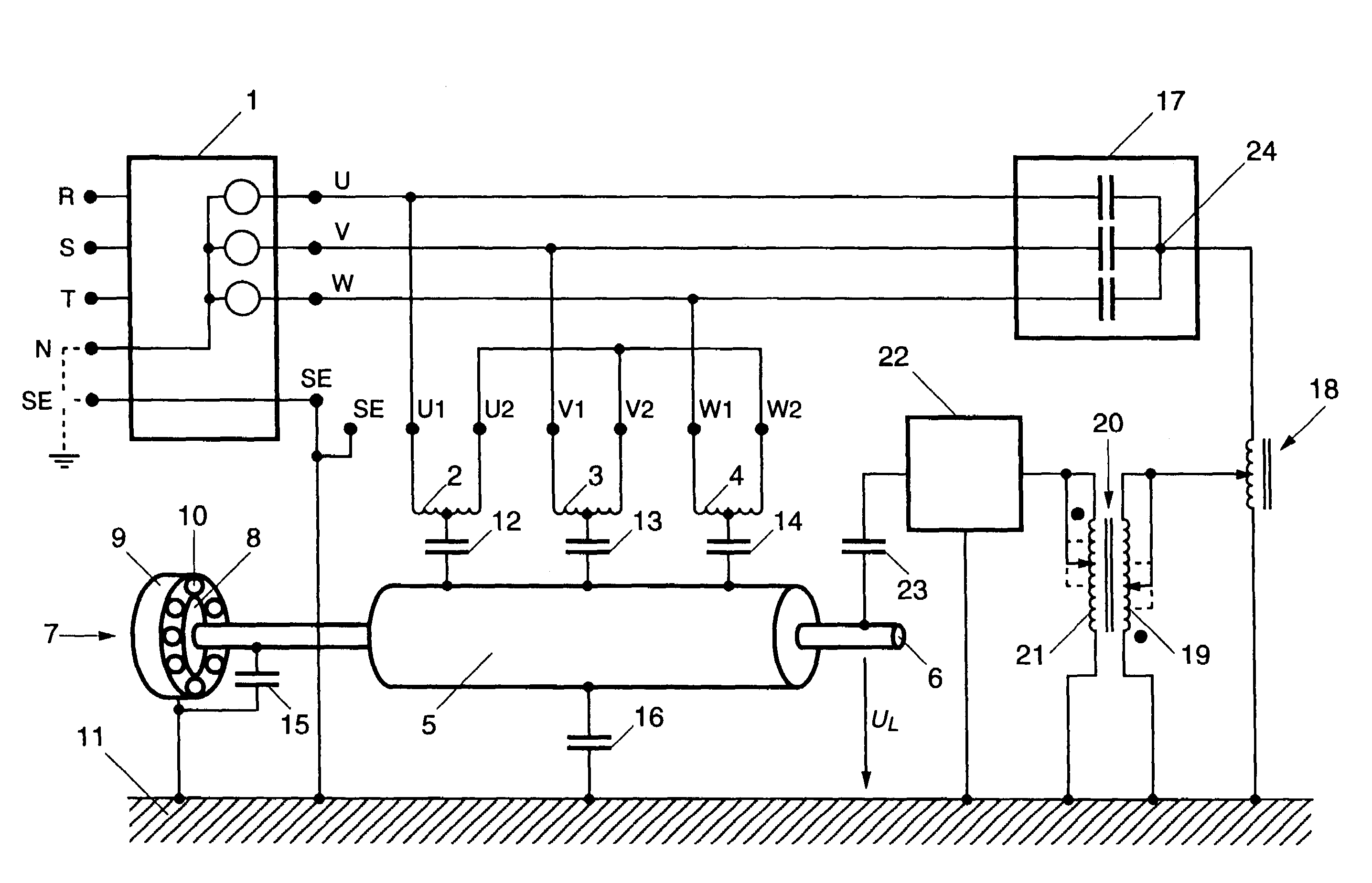
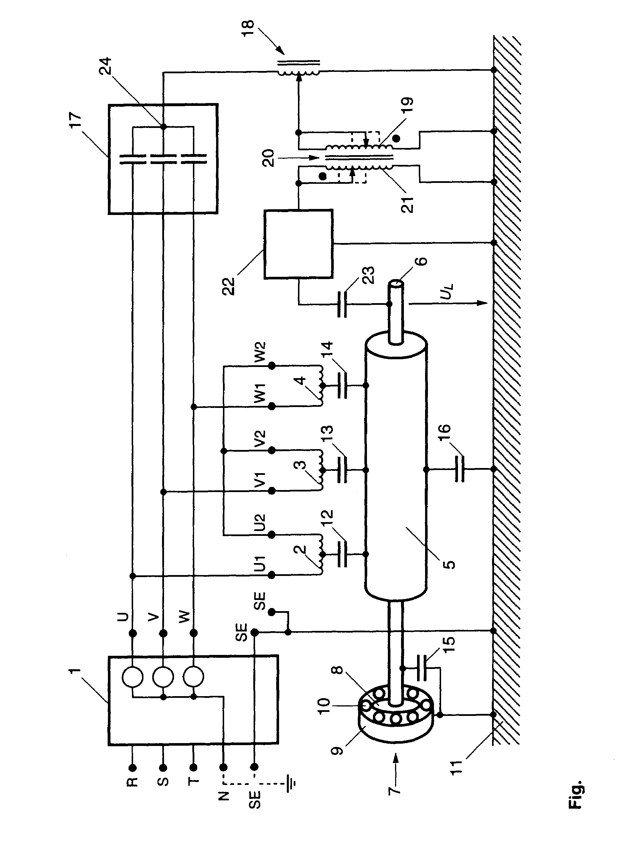
[0009]The present invention has useful application in an electrical machine which has a stator and a rotor which is pivotally mounted by way of a bearing relative to the stator. Generally speaking, a compensation circuit and a coupling element are provided, with the compensation circuit producing a compensation current for the compensation of a parasitic current which arises or is produced during operation of the electrical machine and passes through the bearing and with the coupling element directly or indirectly coupling the compensation current into the bearing.

[0010]This arrangement helps provide relatively reliable protection of the bearing against current passage and thus against the associated potential damage of the bearing. The protective measure arises specifically at the point which is to be protected, specifically on the bearing. In this way the cost for implementation can be kept relatively low as the device in terms of wattage need not be designed for operation of the ...


PUM


Abstract

A device for protecting the bearing of an electrical machine against the damaging passage of current, wherein the electrical machine comprises a stator and a rotor pivotally mounted relative to the stator by the bearing. The device is provided with a compensation circuit which produces a compensation current which compensates for a parasitic current formed during operation of the electrical machine by the bearing and a coupling element for directly or indirectly coupling the compensation current into the bearing.

Description

[0001]This application is based on and claims priority under 35 U.S.C. § 119 with respect to German Application No. 203 01 956.3 filed on Feb. 7, 2003, the entire content of which is incorporated herein by reference.FIELD OF THE INVENTION[0002]This invention generally relates to bearings. More particularly, the invention pertains to a device for protecting the bearing of an electrical machine against the passage of current.BACKGROUND OF THE INVENTION[0003]In electrical machinery, for example electric motors which are pivotally supported by a bearing, there is the danger that current will flow through the bearing and that the associated spark erosion will lead to bearing damage. Current flow through the bearing can be caused by the voltages on the terminals of the electric motor being coupled to the rotor of the electric motor via stray capacitances, for example out of the stator windings. The associated current flows ultimately cause voltage to form on the bearing, which voltage can...

Claims


Application Information

Patent Timeline
IPC IPC(8): H02H5/04H02H7/08G01R31/00G06F19/00H01F30/12H01F38/38H02P29/02H02K5/173H02K11/00
CPCH02K11/0073H02K11/0089H02K5/1732H02K11/33H02K11/40F16C19/52
Inventor PREISINGER, GERWINBUSCHBECK, FRANKGROSCHL, MARTIN
Owner AB SKF
Why Eureka
Try Eureka